
-
-
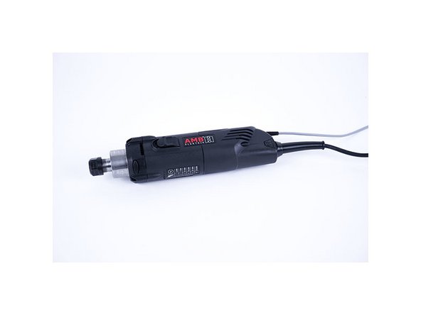
AMB Kress or Mafell spindle with digital control
-
PWM to voltage 0-10V converter (see links)
-
Small wiring cables suitable for 24V
-
-
-
'Disconnect the power supply of the duet controller first!'
-
PWM converter has 4 inputs (2 power + 2 pwm input signals) and 2 outputs (0-10V voltage). Make sure the yellow jumper is on the 24V pins as we are using the duet pwm signal output which is 12/24V.
-
Power wiring to the PWM converter
-
Connect the “VIN” power pin on the duet board (see image) to port 3 on the pwm converter “power supply + (12-30V)”
-
Connect the “GND” power pin on the duet board to port 4 on the pwm converter “power supply – (GND)”
-
Pwm signal wiring to the pwm converter using HEATER E0 of the duet board
-
Connect “VIN” from heater E0 to port 2 “PWM input + (din+)” on the pwm converter
-
Connect “E0-” from heater E0 to port 1 “PWM input – (DIN-)” on the pwm converter
-
-
-
Other than the power supply cable 110V/220V, the spindle has 3 small cables:
-
BROWN 10-26V DC (for power supply)
-
GREEN 0-10V DC (for speed control)
-
WHITE 0 V (for ground/GND)
-
-
-
Brown to “VIN” connector of the duet power supply pin
-
Green to port 6 “voltage output + (AO)” of the pwm converter
-
White to port 5 “ voltage output – (GND)” of the pwm converter
-
Connect port 5 “ voltage output – (GND)” of the pwm converter to the “GND” pin of the power supply on the duet board
-
THE LAST STEP (port 5 to GND pin duet) IS REALLY IMPORTANT! You create a common ground between the spindle and pwm converter/power supply
Yes,
in step 4 of this guide, the last step is:
- connect port 5 "voltage output – (GND)” of the pwm converter to the “GND” pin of the power supply on the duet board
But in step 2 of this guide we have:
- Connect the “GND” power pin on the duet board to port 4 on the pwm converter “power supply – (GND)”
This means that we have 2 cables coming out of “GND” power pin on the duet board. The first one is going to port 5 of PWM converter, and the last one we placed is going to port 4 of PWM converter.
This means that instead of placing this last cable it's easier to link port 4 & 5 on pwm converter.
Hope this is clear...
-
-
-
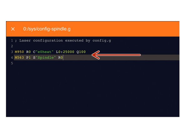
Under File Management > System click on 'config-spindle.g'. Then add the following lines
-
M950 R0 C"e0heat" L0:25000 Q100
-
L is the minimum and maximum RPM of your Spindle. Adjust accordingly.
-
Q is the frequency. If your spindle keeps fluctuating at lower rpms, change the frequency to 300. If it still keeps fluctuating, change it to 320 or 350 and so on.
-
M563 P1 S"Spindle" R0
-
Press the software emergency stop in the top right corner to restart the controller.
Hello Team Ooznest. I own a new Workbee Z1+ and Mafell FM-100 PV. The spindle do not stop and keeps turning at minimum rate (4000 RPM) no matter what. Any idear about the “Q” Frequency setting involved ? I have tried 100 / 300 / 320 / 350 / 600 / 650 … how high does this goes ? Thank You.
Hi Remi,
Have you tried adjusting this line accordingly:
M950 R0 C"e0heat" L0:25000 Q100
So change the L0 to 4000?
Robert -
-
-
-
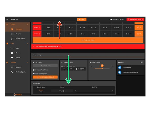
You can control the spindle manually using G-Code.
-
For example M3 S25000, turns the spindle on clockwise and sets the spindle speed at 25000rpm
-
M5 Stops the Spindle.
-
You can also control it in the 'Spindles' panel.
-
Press 'Turn On' will turn the spindle on clockwise at the RPM set.
-
You can change the preset RPMs under Settings > Machine Specific > Spindle RPM Presets.
-
If you have a multimeter, try to read the output voltage of the pwm converter (port 5 and 6). If it says 10V, you are on the maximum spindle speed.
-
You can also add a digital led voltmeter on port 5 and 6 of the pwm controller (see image 2)
I got the “M3: No P parameter and no active tool with spindle” error when trying to type in the code manually. any solutions for this problem?
-
-
-
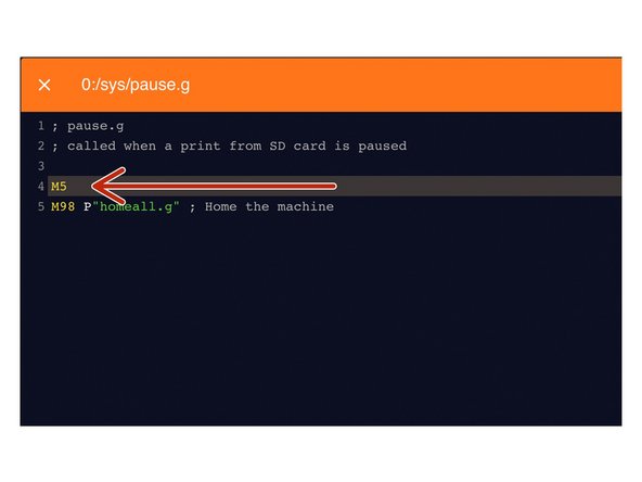
Under File Management > System click on 'pause.g'.
-
Add the command M5 in the header, so the spindle stops when you pause a job while running
-
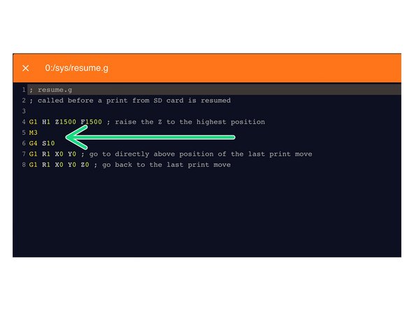
Open the resume.g file and add the following lines
-
M3
-
The Spindle RPM is not needed. It will go back to the RPM when the M5 command was sent.
-
G4 S10
-
Dwell for 10 seconds to let the Spindle get up to speed.
-
-
-
Modify the vectric's post processor to autmatically use spindle speed.
-
Go to the installation directory of the Vectric software, search for “grbl_mm.pp” and make a copy in the same directory and open the copy
-
Change the POST_NAME to something else, I did “GRBL (mm) (SPEED)
-
In the header, change “M3” to “M3[S]” to add speed to the M3 command
-
After your "M3[S]" line, add a new line "G4S15". This code tells the machine to wait 15 seconds to achieve full spindle speed before starting a job
-
Save your file in the post processor directory, make sure it ends with .pp or Vectric does not recognise it!
-
Next time you open the Vectric software, your new post processor will be added to the PP list
-
-
-
Many many thanks to user “Tubal” from the Openbuilds forum, who describes part of the process Openbuilds forum link
-
PWM converter Amazon link
-
Power wiring diagram Duet power wiring
-
AMB Kress wiring diagram from SOROTEC PDF wiring diagram
-
Duet 2 G codes overview Reprap Gcode overview
Upv is the supply from the PSU and needs to be between 8 and 53V,
Us is the signal wire from the PWM converter, and
Uo isn't used.
What I'd like to know is, when will someone explain that the Mafell (or Sorotec) milling motors run at their lowest speed (4,000rpm) when powered up, whether connected to the DI or not?
For anyone connecting a Mafell FM 800 / FM 1000 then the pin outs for the official Mafell cable are :
Pin 1 - Brown - Upv
Pin 2 - White - Us
Pin 3 - Black -Uo
Pin 4 - Blue - Gnd
Now just have to figure out what the Upv , Us , Uo mean
-


Thanks for following the guide. Any issues, please contact us!
Thanks for following the guide. Any issues, please contact us!
Cancel: I did not complete this guide.
5 other people completed this guide.
19 Comments
Hi . step 8- how do i do this using the carveco software ?
thanks
Chris I have implemented this on a Mafell thanks for you hard work on this. Unfortunately it does not respond to the M3 or M5 Gcodes. The speed setting works fine. I am presuming this is a limitation of the Mafell. Or does anybody else know anything different? Or could it be I set the range as specified in the manual like this : M950 R0 C"e0heat" L4000:25000 Q100
Sorry that should have does not switch off with M5 . M3 commands with speed works fine.
For those wanting to connect a Mafell Orginal control cable
Pin 1 : Upv : Brown = power supply (PV Interface)
Pin 2: Us : White = control voltage speed (PV Interface)
Pin 3 : Uo: Black = display remaining runtime in overload mode (PV Interface)
Pin 4: GND: Blue = reference potential for voltages of the PV Interface
Guys, I have Workbee 2.2.1 and this guide - specifically the config part - seems to only apply to Z1. I do not have “config-spindle.g”.
Putting the
M950 C"e0heat" L0:25000 Q100
M563 P1 S"Spindle"
commands in customconfig.g does not work.
The version of these commands with R0 parameter also does not work (I think this is for later firmware). For some reason, I don’t have access to the history of this guide (why is that?), so I have no idea how to apply these to my machine version. Can you help me here?
Hi,
Thanks for your comment. This guide has been updated to the latest version of our firmware. You can update your firmware by following this guide here: How To Update WorkBee Firmware V1.0.7 > V3.3.0-1.2
Once updated the commands in this guide will work.
The Dozuki platform does not allow previous versions of the guides to be public I am afraid.
Robert.
Robert -
You can store spindle speed before pausing and inject it into your resume file
Create a global variable in config-user-settings.g
global spindlespeed = 16000
In pause.g add this line before M5
set global.spindlepeed = spindles.current
In resume.g, the M3 line will read
M3 S{global.spindlespeed}
Hi Andy. Thanks for your suggestion! When M5 is sent the Set spindle speed is already stored by RRF. So I have changed the command in resume.g to just be M3. It will go back to the set RPM when M5 was set. I have also added you suggestion to let the Spindle Dwell for 10 seconds.
Robert -
Also add
G4 S10
After M3 line so spindle can get up to speed before
For anyone who is hesitant to complete this guide don’t be, it is excelent and the spindle works perfectly!
Thanks for posting this guide Christophe, saved me a whole heap of time. I’ve been looking at upgrading to a spindle for my machine and this looks like the ideal solution. I’ll update comment when I’ve got all the kit and installed it.
I found it :
Hi Andy,
I was thinking you asked about the standard amb kress, didn't see it was the one with quickchange, but glad you found it!! Good luck with the installation :-)
Christophe
Thank you for your reply about the AMB 1050 FME-P Di.
I think that the AMB 1050 FME-U DI would need an adapter to be attached to the Z cbeam as the spacing between the fixation holes is 50mm and if 'i’m correct the spacing between the tracks in the cbeam is 2x20 so 40mm. I’ll look for that and if i find it i’ll post it here.
Thank you for this guide. Can you tell me wich router mount is compatible with the AMB 1050 FME or if there is the possibility to mount directly the AMB 1050 FME-U DI on the mounting plate ?
Hello Andy, the openbuilds/ooznest standard router mount needs a reducer to 43mm. Ooznest sells 3D printed router mount adapters.
You can also buy an aluminium router mount 43mm from sorotec.de (without backplate to attach to the Z cbeam) or from makersupplies.dk which has already a backplate to bolt it to the Z cbeam. They're both the same mounts only the German one has no backplate. If your choose the one from sorotec, I can send you the design of the backplate I made myself out of 8mm aluminium.
Greets,
Beickybeer / Christophe
Hello Paul, Have you found a way around this problem ? Everything works fine for me BUT indeed : the mafell does NOT stop. It keeps running at 4000 RPM.
Rémi Duff - Reply
This doesn't work correctly for the Mafell spindle as the Duet outputs 0volts - 10volts for 0 to 25000rpm
Zero volts on the Mafell is 4000rpm.
Paul Tyzzer - Reply