Reputation over time
It looks like this user hasn't gained any reputation yet.
Once they have, you'll be able to view a graph of their reputation gained over time.
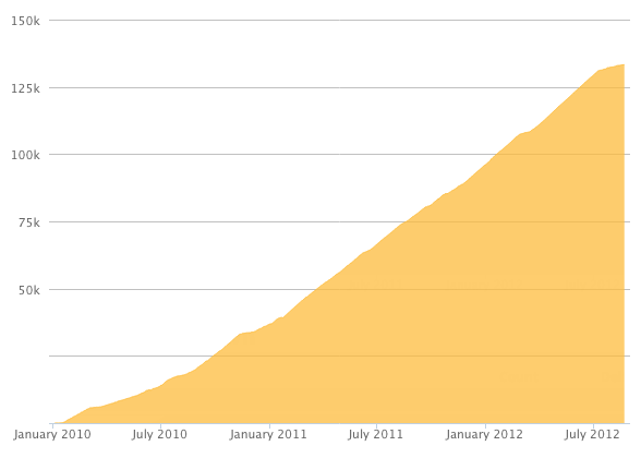
Here's a preview of what the graph will look like:
Reputation Breakdown
No reputation gained yet.
1493
The fan leads could stand to be longer, at least long enough to open the door all the way. I had to support the outer enclosure cover on the extrusion below to plug in the fans.
And yes, the the wire bundle is annoyingly in the way. How about incorporating a tie bar to the enclosure. Maybe a rod that gets installed in front of the duet board from top to bottom after the board is wired.
To keep the bundle of wires away from the fans, I used a several of the little zip ties to secure the wires. They essentially went in front if the wires, up through the SD slot opening, around the back, up through one of the cooling slots, and back to the beginning. Not super tight but just enough to hold things in their space.
Regarding a 1500 x 1500 machine, motor wire 5 needs at the very least 100 mm more just to reach the terminal. And that is without the looming sheath. So maybe 150mm more. As it is right now, the plug end just meets the hole and there is zero slack in the line from the motor to the entry hole on the controller housing. Before you ask, the wire from the stepper motor is at the bottom position. Limit switch 0 and 2 would also benefit from having 80-100 mm more in length. If I zip tied limit switch 2 to extrusion B as instructed, then it is too short. As it is, if you had to re-terminate a wire, there is zero service loop length.
Pull the Z limit switch and touch probe wires through now or pull a second string the chain for the coming steps.
The instructions state "through each hole" (four holes) but the drawing shows only two screws. Guys are visual oriented, make the two match.
A torque value would be great here rather than do not over tighten.
Limit switches are identified with a number around the wires near the white plug.
You drawing of the X-Plate-Front causes a bit of uncertainty. It looks like the holes adjacent to the limit switch location are counterbored on the back side.
Please add a note that the eccentric spacers fit one side only.
Add a second exploded drawing with item bubbles identifying hardware. Item bubble number should correspond to a distinct number from the bill of materials and include that number on the hardware kits/bags instead of using the names (or with the names).
Include torque values for screws.
I watched the Erie guys video and it was helpful. Being in the states, I didn't have a 5mm screw laying around, but a 3/16" drill bit and a couple pieces of wood did the trick. One piece of wood had a through hole, the other with a blind hole, both drilled with the 3/16" bit. After boring the holes, the drill bit shank was placed into the blind hole. Then, like in the video, you stack the bearing, shim, wheel, & second bearing onto the drill bit followed by the second piece of wood and squeeze the assembly together. Worked like a charm.