
-
-
WorkBee Kits may include different version drag chains, please refer to the correct drawings for assembly of the version supplied.
-
Attach a Drag-Chain-Fixed-End to the Y-Drag-Chain-Fixed-End-Mount in the orientation shown above, using 3 x M5-Low-Profile-15mm bolts and 3 x M5-Nyloc-Nuts.
-
Attach a Drag-Chain-Fixed-End to the Y-Drag-Chain-Fixed-End-Mount in the orientation shown above, using 2 x M5-Low-Profile-15mm bolts and 2 x M5-Nyloc-Nuts.
-
-
-
Position the Y-Axis-Fixed-End-Assembly to the back left corner of the WorkBee.
-
It should be flush with the end of the C-Beam-750mm. Secure it using 2 x M5-Low-Profile-25mm bolts and 2 x M5-Drop-In-Tee-Nuts.
-
-
-
WorkBee Kits may include different version drag chains, please refer to the correct drawings for assembly of the version supplied.
-
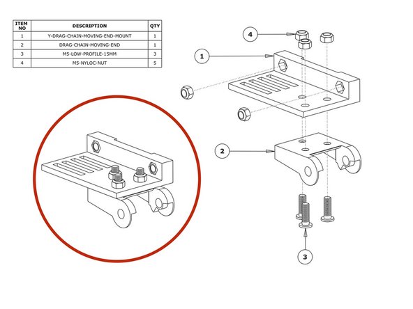
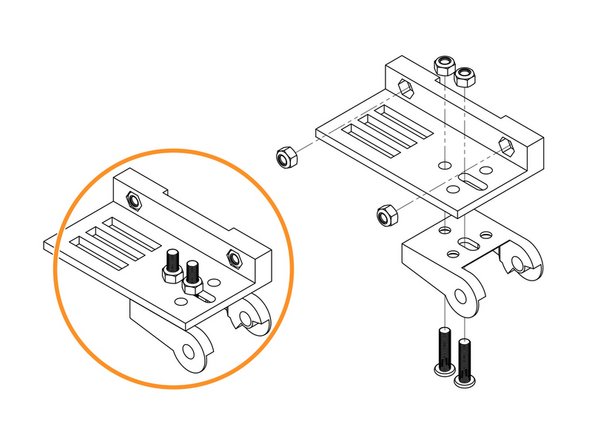
Insert 2 x M5-Nyloc-Nuts into the insets on the Y-Drag-Chain-Moving-End-Mount. They are a snug fit, so may require a light tap with a hammer.
-
Attach a Drag-Chain-Moving-End to the Y-Drag-Chain-Moving-End-Mount in the orientation shown above using 3 x M5-Low-Profile-15mm bolts and 3 x M5-Nyloc-Nuts.
-
Attach a Drag-Chain-Moving-End to the Y-Drag-Chain-Moving-End-Mount in the orientation shown above using 2 x M5-Low-Profile-15mm bolts and 2 x M5-Nyloc-Nuts.
-
-
-
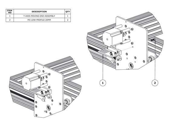
Secure the Y-Axis-Moving-End-Assembly using 2 x M5-Low-Profile-20mm bolts and the 2 x M5-Nyloc-Nuts already inserted into Y-Drag-Chain-Moving-End-Mount.
-
-
-
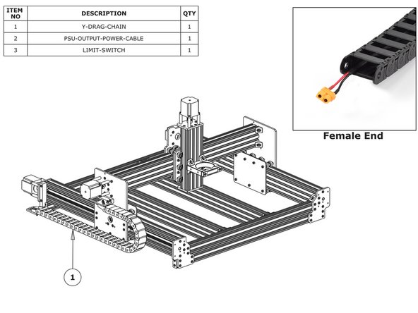
Lay the Y-Drag-Chain flat on a table. Feed the PSU-Output-Power-Cable through the whole length of the Y-Drag-Chain. Ensure that the end with the XT60-Connector, is located at the female end of the Y-Drag-Chain. (as shown in the ‘Female End’ image).
-
If you have a screw driven WorkBee feed the two Y-Axis motor wires through the Y Drag-Chain. The end of the stepper motor wires with the black connector should be at the female end of the Y-Drag-Chain - same as above.
-
Feed the wires on the Y-Axis Limit-Switch, through the Y Drag-Chain. The switch portion of the Limit-Switch should be at the female end of the Y-Drag-Chain.
-
Lay the Y-Drag-Chain flat along the left side of the WorkBee. The female end of the Y-Drag-Chain should be at the back of the machine, and the male end at the front.
-
Attach the female end of the Y-Drag-Chain to the Drag-Chain-Fixed-End on the Y-Axis Fixed-End-Assembly. It will take some force to click it into the Drag-Chain-Fixed-End.
-
Bring the male end of the Y-Drag-Chain to the Y-Axis-Moving-End-Assembly and attach it to the Drag-Chain-Moving-End. It will take some force to click it into the Drag-Chain-Moving-End.
-


Thanks for following the guide. Any issues, please contact us!
Thanks for following the guide. Any issues, please contact us!
Cancel: I did not complete this guide.
36 other people completed this guide.