
-
-
Attach a Drag-Chain-Fixed-End to the Y-Drag-Chain-Fixed-End-Mount in the orientation shown above, using 3 x M5-Low-Profile-15mm bolts and 3 x M5-Nyloc-Nuts.
-
-
-
Position the Y-Axis-Fixed-End-Assembly to the back left corner of the WorkBee.
-
It should be flush with the end of the C-Beam-750mm. Secure it using 2 x M5-Low-Profile-25mm bolts and 2 x M5-Drop-In-Tee-Nuts.
-
-
-
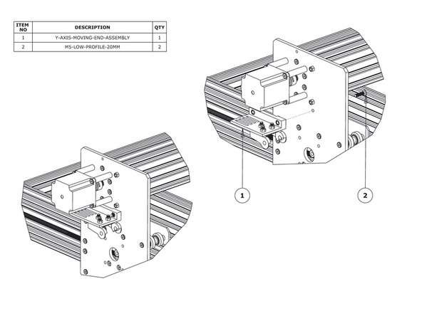
Insert 2 x M5-Nyloc-Nuts into the insets on the Y-Drag-Chain-Moving-End-Mount. They are a snug fit, so may require a light tap with a hammer.
-
Attach a Drag-Chain-Moving-End to the Y-Drag-Chain-Moving-End-Mount in the orientation shown above using 3 x M5-Low-Profile-15mm bolts and 3 x M5-Nyloc-Nuts.
-
-
-
Secure the Y-Axis-Moving-End-Assembly using 2 x M5-Low-Profile-20mm bolts and the 2 x M5-Nyloc-Nuts already inserted into Y-Drag-Chain-Moving-End-Mount.
-
-
-
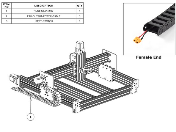
Lay the Y-Drag-Chain flat on a table. Feed the PSU-Output-Power-Cable through the whole length of the Y-Drag-Chain. Ensure that the end with the XT60-Connector, is located at the female end of the Y-Drag-Chain. (as shown in the ‘Female End’ image).
-
If you have a screw driven WorkBee feed the two Y-Axis motor wires through the Y Drag-Chain. The end of the stepper motor wires with the black connector should be at the female end of the Y-Drag-Chain - same as above.
-
Feed the wires on the Y-Axis Limit-Switch, through the Y Drag-Chain. The switch portion of the Limit-Switch should be at the female end of the Y-Drag-Chain.
-
Lay the Y-Drag-Chain flat along the left side of the WorkBee. The female end of the Y-Drag-Chain should be at the back of the machine, and the male end at the front.
-
Attach the female end of the Y-Drag-Chain to the Drag-Chain-Fixed-End on the Y-Axis Fixed-End-Assembly. It will take some force to click it into the Drag-Chain-Fixed-End.
-
Bring the male end of the Y-Drag-Chain to the Y-Axis-Moving-End-Assembly and attach it to the Drag-Chain-Moving-End. It will take some force to click it into the Drag-Chain-Moving-End.
-


Thanks for following the guide. Any issues, please contact us!
Thanks for following the guide. Any issues, please contact us!
Cancel: I did not complete this guide.
30 other people completed this guide.
2 Comments
I would advise fitting the ‘Y drag chain moving end mount’ onto the X axis endplate before assembling to the C - beam. I found that it is very difficult to get an alan key on the head of the rear bolt and turn it for tightening. There just not enough room in between the beams. Either that or use tapped holes in the X axis end plate and fix the ‘Y drag chain moving end mount’ with low profile M5 screws from the outside ( do away with the nyloc nuts).
Paul Clements - Resolved on Release Reply