
Introduction
Please read before proceeding to avoid damaging the controller and voiding your warranty
- Avoid connecting the Controller via USB when you do not need to. (Except when instructed to in the guides)
- Always unplug the WorkBee Power Supply before connecting the USB Cable.
-
-
The Emergency Stop has been pre-tested by Ooznest. But you should test it again.
-
First insure the machine is switched on, and have WorkBee Control open on your web browser.
-
Press the Emergency Stop.
-
You should loose connection to WorkBee Control.
-
If you do not loose connection make sure the USB Cable is not plugged in.
-
If you still do not loose connection, stop here and Contact Us.
-
With the connection lost, unlatch the Emergency Stop.
-
After a few seconds WorkBee Control should reconnect.
-
-
-
If looking at the machine from the front the axis motion is:
-
The X-Axis is positive towards the right.
-
The Y-Axis is positive towards the back.
-
The Z-Axis is positive going up.
-
-
-
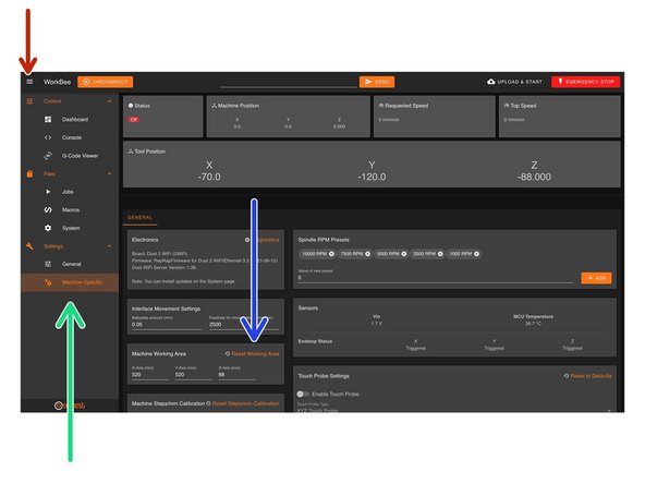
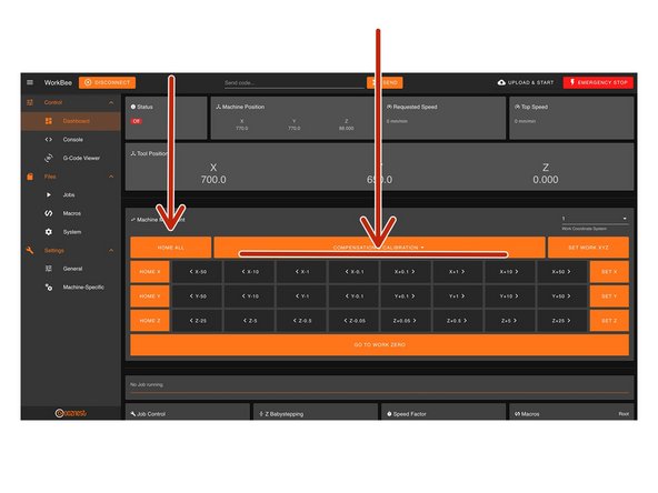
In WorkBee Control open the Navigation Menu
-
Under 'Settings', press 'Machine Specific'
-
Under the Panel called 'Machine Working Area' press 'Reset Working Area'
-
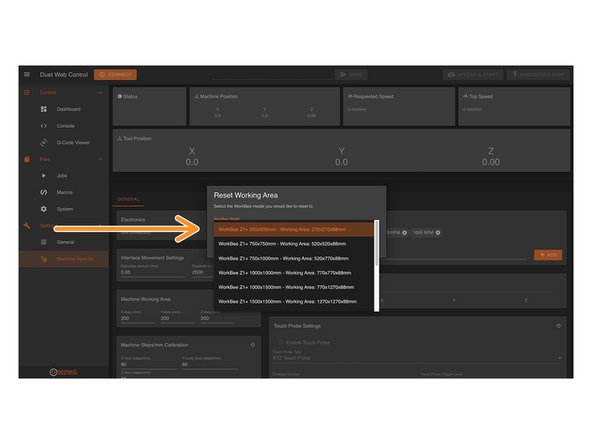
Under the 'WorkBee Model' dropdown select your machine size.
-
Yours is a Z1+ Model
-
Confirm by pressing 'Yes'
-
The machine is now configured. No restart required.
-
-
-
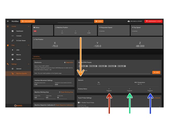
On the same page, under the Panel called 'Sensors' we can test the Limit Switches.
-
Activate the X-Axis limit switch with your finger and hold.
-
The Endstop Status should change to 'Triggered'
-
It is normal for there to be a delay between pressing the limit switch and the status being updated. Please do not be concerned, the board will stop the motor instantaneously.
-
Repeat this procedure for the Y-Axis Limit Switch.
-
Repeat this procedure for the Z-Axis Limit Switch.
-
If any do not behave as intended do not proceed with this guide, please Contact Us.
-
-
-
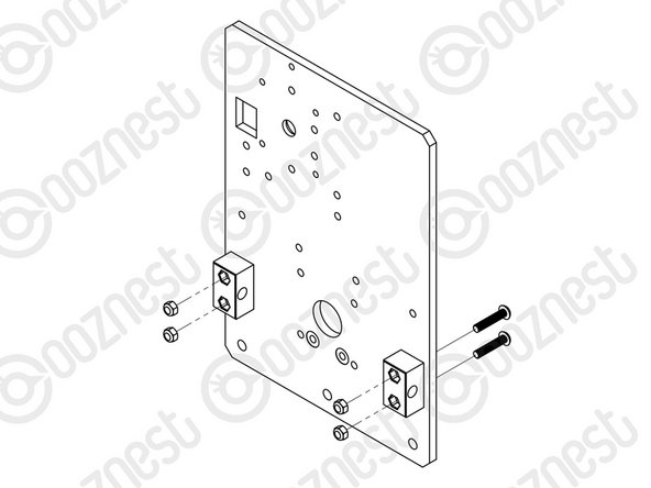
At this point in time, the Nut Blocks on X & Y-Axis Carriages should be loose.
-
Tighten these.
-
Do not over tighten them, they will need to be undone shortly.
-
-
-
When the machine homes, it will raise the Z-Axis, and then move the X and Y-Axis to the far right-hand corner.
-
If any of the points below do not behave as explained do not proceed with this guide, please Contact Us.
-
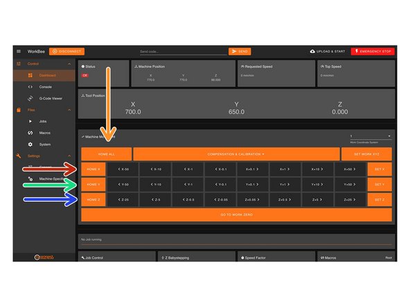
Press Home Z. The Z-Axis should raise upwards, bounce once on the limit switch, and then stop.
-
Press Home X. The Z-Axis should home like the previous. The X-Axis should then move towards the right, bounce once on the limit switch, and then stop.
-
Press Home Y. The Z-Axis should home like previous. The Y-Axis should then move towards the back, bounce once on the limit switch, and then stop.
-
Press Home All. The Z-Axis should home like previous. Then the X and Y-Axis should home like previous.
-
-
-
Home the machine and use the jog buttons to move the machine roughly into the middle of the working area in X & Y.
-
Leave the machine powered on so the Stepper-Motors stay locked.
-
If at any point in Step 7, 8 or 9 you loose power to motors and need to re-lock the motors, go to Control > Console and send the command 'M17'
-
Loosen all the Nut-Blocks on the X & Y-Carriages.
-
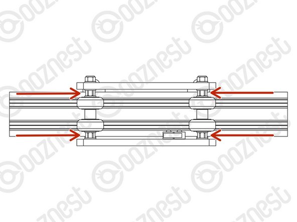
Loosen the Clamping-Collars that are on the inside channel of Extrusion-E/F on the X & Y Axes.
-
Move the Rubber-Bushings & Clamping-Collars away from the plates.
-
-
-
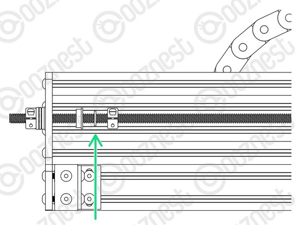
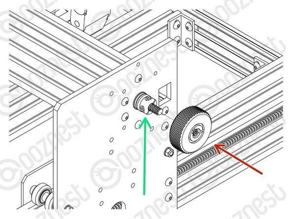
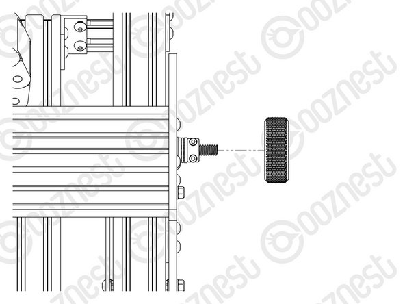
Starting with the X-Axis, thread on the Tensioning-Knob until it is up against the Clamping-Collar.
-
Then loosen the same Clamping-Collar.
-
Turn the Tensioning-Knob clockwise, you will feel the Lead-Screw tension build.
-
Keep turning until the Stepper-Motor clicks over.
-
Keep turning, just before the point that the Stepper-Motor clicks over again is the correct amount of tension for the Lead-Screw.
-
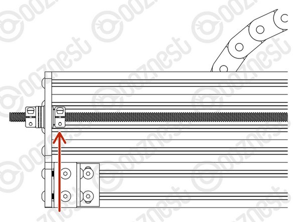
While at this point of tension, tighten the Clamping-Collar that is next to the Tensioning-Knob.
-
Remove the Tensioning-Knob.
-
Repeat all the above for both Lead-Screws on the Y-Axis.
-
-
-
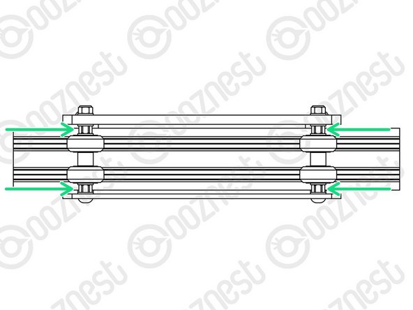
Once all 3 Lead-Screws are tensioned, put back the Flanged-Radial-Bearings, Rubber-Bushings, and Clamping-Collars that are on the inside channel of Extrusion-E/F on the X & Y Axes.
-
The Clamping-Collars only need to be pushed lightly up against the Rubber-Bushings & Flanged-Radial-Bearings. Tighten the Clamping-Collars.
-
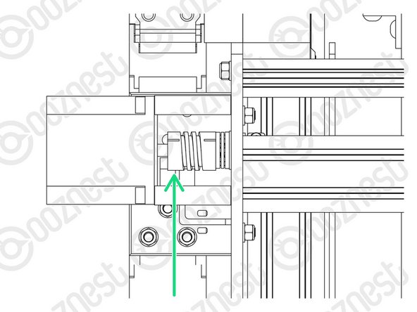
We need to release any tension inside the Flexible-Couplers.
-
On the Stepper-Motor side of the X & Y-Axis Flexible-Couplers completely loosen the grub screws and clamping bolts.
-
Then completely tighten the same grub screws and clamping bolts.
-
Make sure you do this to the Stepper-Motor side of the Flexible-Coupler.
-
If you loosen the Lead-Screw side you will loose all tension in the Lead-Screws and you will need to redo it.
-
Tighten all the Nut-Blocks on the X & Y-Carriages. While doing so, squeeze the Nut-Blocks together to remove any backlash.
-
-
-
Home the machine.
-
Then turn the machine off.
-
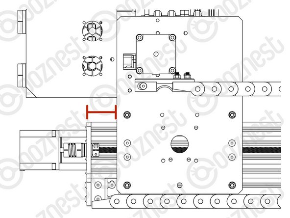
On the left Y-Axis (The side with the Limit-Switch) measure the distance between the back of the Y-Carriage and Y-End-Plate.
-
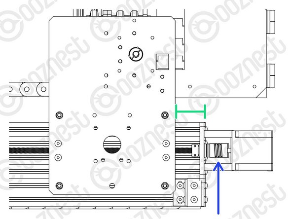
On right Y-Axis measure the same distance.
-
Rotate the Flexible-Coupler by hand until it matches the left Y-Axis.
-
-
-
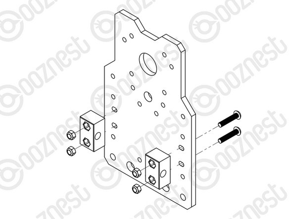
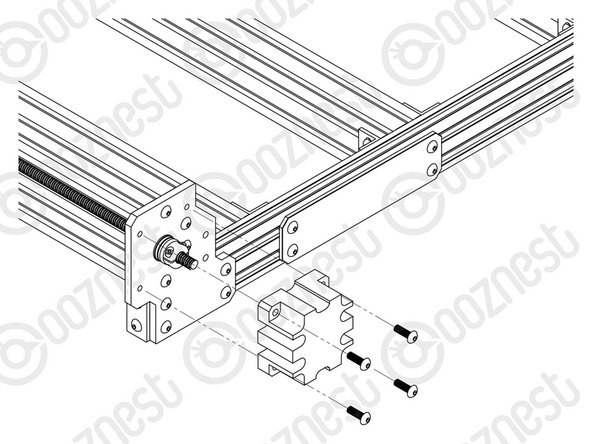
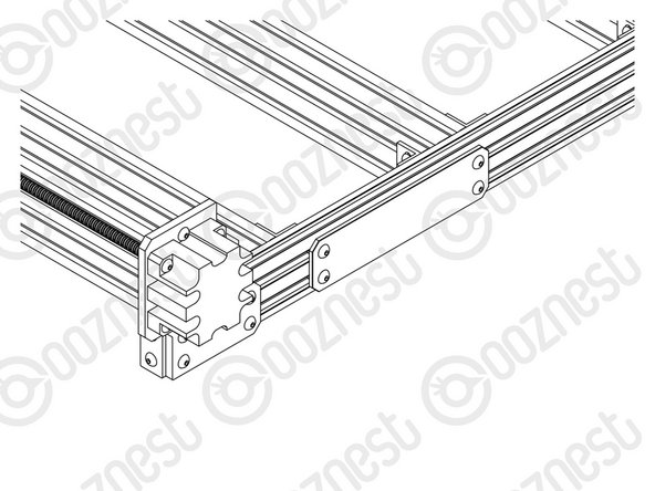
Using 12 x M5-Button-Head-Bolt-16mm attach 3 x Lead-Screw-Caps over the bare ends of the X & Y-Axis Lead-Screws.
-
-
-
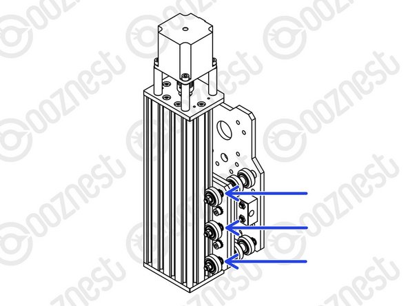
In the 'Extras' box there is an Eccentric-Spacer-Spanner.
-
This is shaped to give you access to all the Eccentric-Spacer-6mms without needing to move your machine.
-
Eccentric-Spacer-6mms should be adjusted until there is a small amount of friction between the Solid-Wheel & Extrusion.
-
Check there is also no play in the carriage if you try to wobble it. The Eccentric-Spacer-6mm will remove this if adjusted correctly.
-
Adjust the Eccentric-Spacers on the X-Carriage.
-
Adjust the Eccentric-Spacers on both Y-Carriages.
-
Adjust the Eccentric-Spacers on the Z-Axis.
-
We recommend periodically checking the Eccentric-Spacer-6mms throughout the use of the machine.
-
-
-
It is nice to finally start moving the machine!
-
Guide Complete - Proceed to 3. Spoilerboard
-


Thanks for following the guide. Testing of the WorkBee is now complete!
Thanks for following the guide. Testing of the WorkBee is now complete!
Cancel: I did not complete this guide.
44 other people completed this guide.

2 Comments
Using 16 x M5-Button-Head-Bolt-16mm attach 3 x Lead-Screw-Caps over the bare ends of the X & Y-Axis Lead-Screws.
This had me hunting around trying to find 16x M5 16mm bolts for a good five minutes before I realised that three caps with four bolts each only needed twelve total. Somehow I only had six, so each one got two.
Jack O'Hara - Resolved on Release Reply