
-
-
Attach 2 x ACME-Nut-Blocks to one of the Y-Plates using 4 x M5-Low-Profile-25mm bolts & 4 x M5-Nyloc-Nuts.
-
Only loosely tighten these bolts so the ACME-Nut-Blocks can still move side to side.
-
Thread a Y-ACME-Lead-Screw through both ACME-Nut-Blocks. Tighten the bolts holding one of the ACME-Nut-Blocks, making sure it is square to the Y-Plate.
-
To remove any backlash, pinch the loose ACME-Nut-Block towards the previous one, and tighten the bolts holding it.
-
Leave the Y-ACME-Lead-Screw threaded through the ACME-Nut-Blocks.
-
-
-
First attach the bottom right wheel set; insert a M5-Low-Profile-60mm bolt through the Y-Plate-Assembly from the back. On to this bolt, add an Eccentric-Spacer-6mm, Precision-Shim, Solid-V-Wheel-Xtreme-Assembly, Aluminium Spacer-9mm, Solid-V-Wheel-Xtreme-Assembly, Precision Shim, and a Eccentric-Spacer-6mm in this order.
-
Next, add a Y-Plate-Inner onto the top of this assemblage, add a Precision-Shim and then slightly thread on a M5-Nyloc-Nut. The rounded portion of the Eccentric-Spacer-6mm should be inserted into the hole on either the Y-Plate-Assembly or Y-Plate-Inner (depending on which side it is on).
-
Repeat for the other wheel set on the bottom row corner.
-
Repeat for the 2 wheel sets on the top row, however for these sets use Aluminium-Spacer-6mms instead of Eccentric-Spacer-6mms.
-
Once all of the wheels are attached the M5-Nyloc-Nuts can be tightened down. Ensure that the Solid-V-Xtreme-Wheels can still rotate freely. On the hexagonal portion of the Eccentric-Spacer-6mm, there will be one face that is marked with ‘6mm’.
-
Using a spanner, adjust each Eccentric-Spacer-6mm so that this face is facing downwards. Doing this maximizes the gap between the top and bottom row of wheels.
-
Try to get all the wheels touching the aluminium extrusion as best as possible. It is not a problem, if there is one wheel which is slightly looser than the others. After the machine has been operational for a little while, they will bed in.
-
-
-
Run any piece of C-Beam extrusion in-between the two rows of wheels. Initially, there may be a small amount of play between the C-Beam and wheels. Turn the assembly upside down so the C-Beam is sitting on the row of wheels with the Aluminium-Spacer-6mms.
-
Starting with one pair of wheels, adjust both Eccentric-Spacer-6mms down onto the C-Beam Extrusion until there is a small amount of friction between both wheels and the C-Beam Extrusion.
-
When adjusting the pair of Eccentric-Spacer-6mms ideally they should be adjusted identically. However, sometimes one will need to be adjusted slightly more than the other to get both wheels engaged with the C-Beam extrusion.
-
Repeat for the other pair of wheels with eccentric spacers.
-
Slide the C-Beam extrusion back and forth through the wheels. This should require a small amount of force, and all wheels should spin as it rolls. Also check there is no wobbling of the extrusion. Once happy, double check the tightness of the M5-Nyloc Nuts.
-
-
-
Repeat the this section for other Y-Plate. As seen it should be a mirror image of the previous assembly.
-
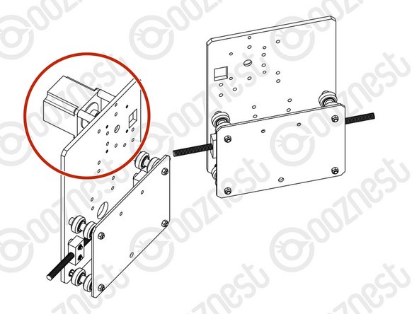
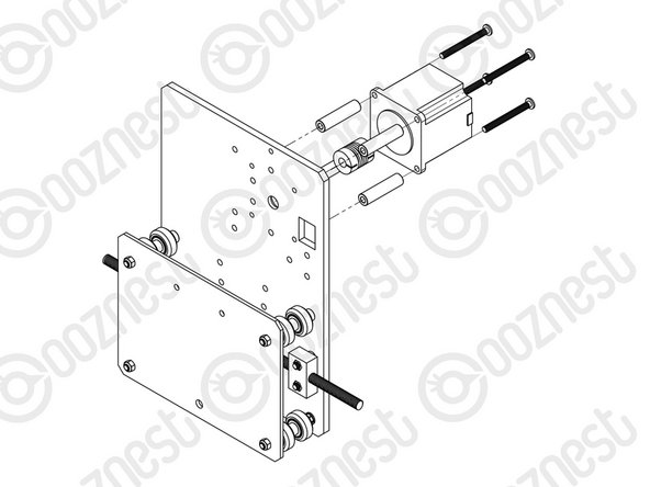
A NEMA23-Stepper-Motor needs to be attached to the second Y-Plate Assembly. See pictures 2 & 3.
-
Slide the 1/4” side (the side with the smallest hole) of the Flexible-Coupler onto the shaft of the NEMA23-Stepper-Motor. Don’t tighten it down at this point.
-
Attach the NEMA23-Stepper-Motor to the threaded holes on the Y-Plate using 4 x M5-Low-Profile-50mm bolts and 4 x Aluminium-Spacer-40mm’s.
-
Orient the NEMA23-Stepper-Motor so that the wire is towards the back of the Y-Plate (the side closet to the small rectangle opening).
-
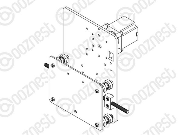
The Y-Plate Assembly with the NEMA23-Stepper-Motor will be known going forward as the Y-Plate-Left Assembly.
-
The other Y-Plate Assembly (Without the NEMA23-Stepper-Motor) will be known going forward as the Y-Plate-Right Assembly.
-


Thanks for following the guide. Any issues, please contact us!
Thanks for following the guide. Any issues, please contact us!
Cancel: I did not complete this guide.
57 other people completed this guide.

2 Comments
Hi ooznest!
Our machine is fully built and operational now but have a query: Is there a specific reason the eccentric nuts are placed on the lower part of the carriage? We found that when installing the spoiler board supports and when fixing the machine down with the supplied brackets, we had a bit of movement, only tiny but enough to require adjustment of the eccentric nuts. Once its bedded down, its incredibly difficult getting a spanner in to make adjustments, however if the eccentric nuts were on the top wheels of the carriage, they’d be easy to get to. Is there a reason they’re on the bottom or could they be installed on top?
Tyler Clark - Resolved on Release Reply
A good method of adjusting the cams to fit the z axis c beam is to turn each of the 4 wheels in turn ensuring it moves the c beam without slipping. This ensures each wheel is in contact with the c beam.
Paul Howes - Resolved on Release Reply