
-
-
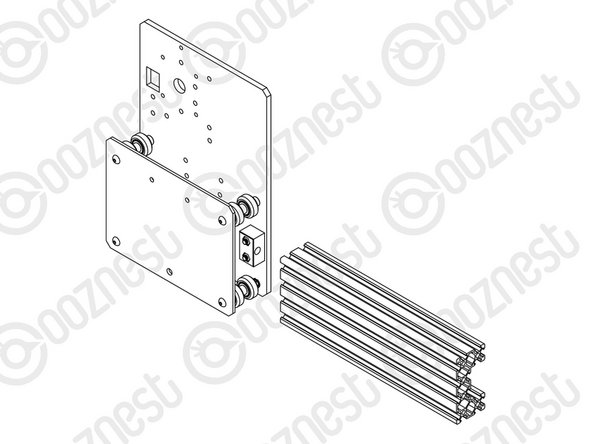
Attach 2 x Nut-Blocks to a Y-Plate-Outer using 4 x M5-Button-Head-Bolt-25mm & 4 x M5-Nyloc-Nuts.
-
Keep these bolts loose so the Nut-Blocks can still move side to side.
-
-
-
Assemble the bottom right Solid-Wheel set first. Insert a M5-Button-Head-Bolt-60mm through the Y-Plate-Inner
-
On to the bolt add an Eccentric-Spacer-6mm. (Rounded portion into the Y-Plate-Inner)
-
Then add a Precision-Shim - ->- - Solid-Wheel - ->- - Aluminium-Spacer-9mm - ->- - Solid-Wheel - ->- - Precision-Shim
-
Add an Eccentric-Spacer-6mm then a Y-Plate-Outer. (Rounded portion of the Eccentric-Spacer-6mm goes into the Y-Plate-Outer)
-
On the outside of the Y-Plate-Outer add onto the bolt a Precision Shim then a M5-Nyloc-Nut. Only slightly thread on the M5-Nyloc-Nut.
-
Repeat the above for the other Solid-Wheel set on the bottom row.
-
Repeat for the 2 x Solid-Wheel sets on the top row, but use a Aluminium-Spacer-6mm instead of each Eccentric-Spacer-6mm.
-
The M5-Nyloc-Nuts can now be tightened. Ensure that each Solid-Wheel still rotates freely.
-
-
-
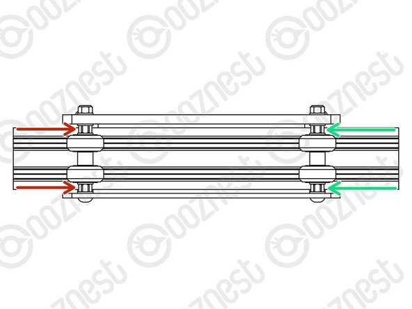
On the hexagonal portion of the Eccentric-Spacer-6mm, there will be a face that is marked with ‘6mm’.
-
Using a 8mm spanner, rotate each Eccentric-Spacer-6mm so that this face is facing downwards. (Doing this maximises the gap between the top and bottom row of Solid-Wheels)
-
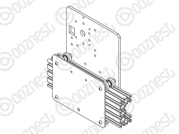
Insert Extrusion-D in-between the two rows of wheels. Turn the assembly upside down so Extrusion-D is sitting on the top row of Solid-Wheels.
-
Rotate both Eccentric-Spacer-6mms on one set of Solid-Wheels until there is a small amount of friction between the Solid-Wheels and Extrusion-D
-
Repeat for the other set of Solid-Wheels.
-
Slide Extrusion-D back and forth. This should require a small amount of force, and all Solid-Wheels should spin.
-
Check there is no wobbling of Extrusion-D. Once happy, double-check the tightness of the M5-Nyloc Nuts and remove Extrusion-D.
-
Try to get all the Solid-Wheels touching Extrusion-D as best as possible. If not, it is not a problem, we will check the Eccentric-Spacers-6mms again once the machine is built.
-
-
-
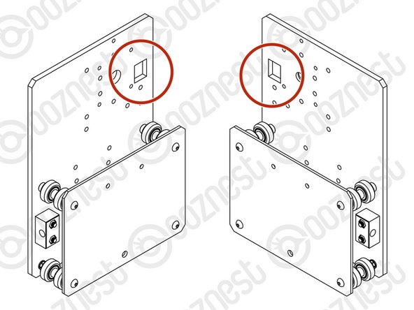
Repeat Steps 1-3 for another Y-Plate Assembly. It should be a mirror image of the previous assembly.
-
Ensure the square cut out on the Y-Plate-Outer is at the back.
-
-
-
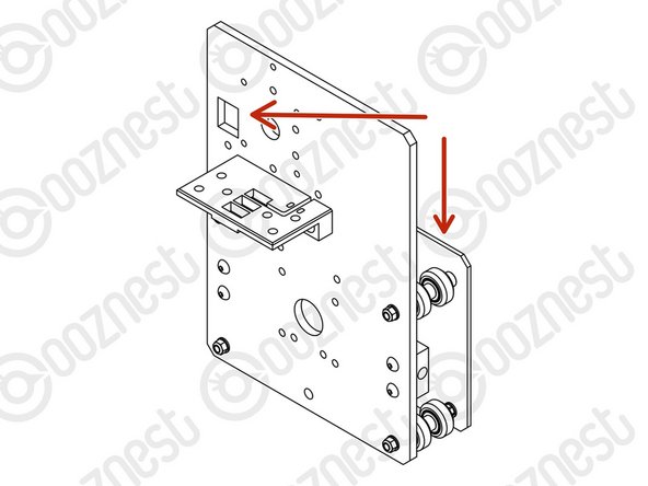
A Drag-Chain-Mount needs to be attached to the second Y-Plate-Outer.
-
Make sure you have the correct Y-Plate-Outer.
-
The square cut out on the Y-Plate-Outer is at the back with the wheels on the opposite side.
-
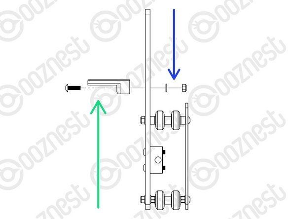
Insert 2 x M5-Button-Head-Bolt-16mms through the Drag-Chain-Mount, then through the Y-Plate-Outer.
-
Then add a 2 x Precision-Shims and 2 x M5-Nyloc-Nuts on the opposite side of the Y-Plate-Outer.
-
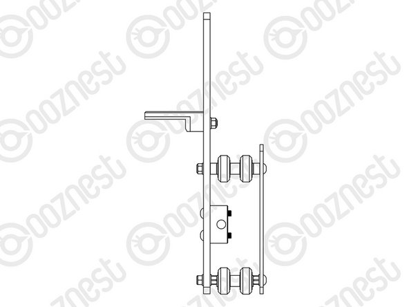
Moving forward this will be known as the Y-Carriage-Left.
-
The other one will be known as the Y-Carriage-Right.
-
-
-
The Y-Carriages can be put to one side until later.
-
Guide Complete - Proceed to 3. X-Carriage Assembly
-


Thanks for following the guide. Any issues, please contact us!
Thanks for following the guide. Any issues, please contact us!
Cancel: I did not complete this guide.
102 other people completed this guide.

3 Comments
On page 3 it incorrectly implies that you use ‘eccentric’ spacer 6mm on the top & bottom wheel sets - it should say ‘aluminium’ spacer 6mm (I think?!)
Jim Cooper - Resolved on Release Reply