
-
-
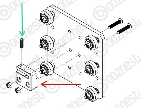
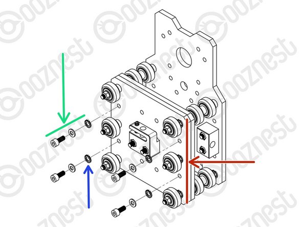
Assemble the top right Solid-Wheel set first. Insert a M5-Button-Head-Bolt-30mm through the Z-Plate from the back.
-
The back is the side with the counterbores.
-
On to the bolt add an Eccentric-Spacer-6mm. (Rounded portion into the Z-Plate)
-
Then add a Precision-Shim - ->- - Solid-Wheel - ->- - Precision-Shim
-
Finally add a M5-Nyloc-Nut. This can be tightened. Ensure that the Solid-Wheel still rotates freely.
-
Repeat the above for the other 2 x Solid-Wheel set on the right row.
-
Repeat for the 3 x Solid-Wheel sets on the left row, but use a Aluminium-Spacer-6mm instead of each Eccentric-Spacer-6mm.
-
-
-
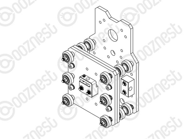
On the hexagonal portion of the Eccentric-Spacer-6mm, there will be a face that is marked with ‘6mm’.
-
Using a 8mm spanner, rotate each Eccentric-Spacer-6mm so that this face is facing right. (Doing this maximises the gap between the left and right row of Solid-Wheels)
-
Insert Extrusion-D in-between the two rows of wheels. Turn the assembly on to it's left side so Extrusion-D is sitting on the left row of Solid-Wheels.
-
Starting with the top right Solid-Wheel. Rotate the Eccentric-Spacer-6mm until there is a small amount of friction between the Solid-Wheel and Extrusion-D
-
Repeat for the bottom right Solid-Wheel. Then repeat for the middle right Solid-Wheel.
-
Slide Extrusion-D back and forth. This should require a small amount of force, and all Solid-Wheels should spin.
-
Check there is no wobbling of Extrusion-D. Once happy, double-check the tightness of the M5-Nyloc Nuts and remove Extrusion-D.
-
Try to get all the Solid-Wheels touching Extrusion-D as best as possible. If not, it is not a problem, we will check the Eccentric-Spacers-6mms again once the machine is built.
-
-
-
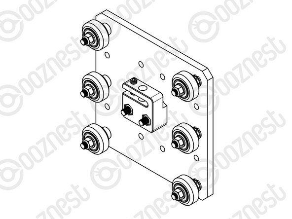
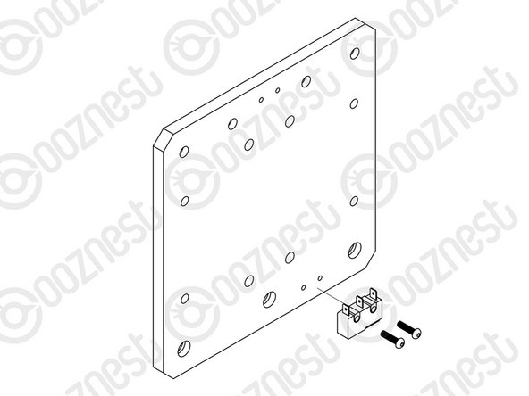
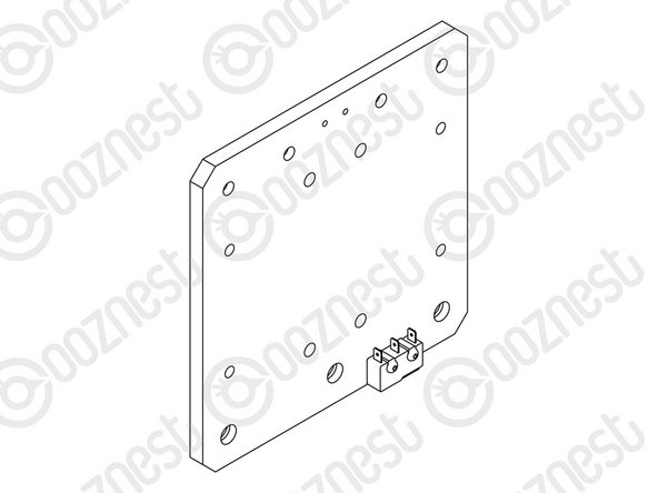
Attach the Z-Axis-Nut-Block to the Z-Plate using 2 x M5-Button-Head-Bolt-25mm & 2 x M5-Nyloc-Nuts.
-
In the Z-Axis-Nut-Block bag there is a set screw. Screw it into the top of the Z-Axis-Nut-Block until it just touches the surface on the opposite side of the gap.
-
The set screw will later be used to remove any backlash from the Z-Axis.
-
Discard the nut left in the bag with the Z-Axis-Nut-Block.
-
Moving forward this will be known as the Z-Plate-Assembly
-
-
-
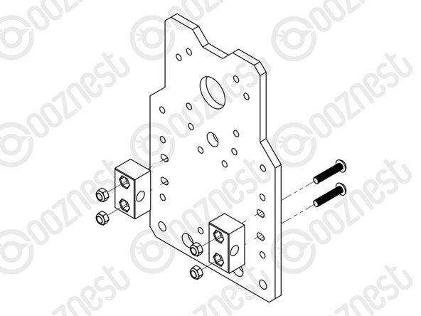
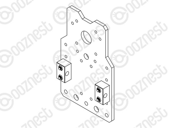
Attach 2 x Nut-Blocks to the X-Plate-Back using 2 x M5-Button-Head-Bolt-25mm & 2 x M5-Nyloc-Nuts.
-
Keep these bolts loose so the Nut-Blocks can still move side to side.
-
-
-
The Limit-Switches are located in the 'Wires' box. They have red/black wires attached to them. The wires are not shown in the assembly picture.
-
Attach the Limit-Switch-2 to the threaded holes on the back of the X-Plate-Front using 2 x M2.5-Button-Head-Bolt-10mm.
-
The back is the side without the counterbores.
-
Look at the Cheat Sheet to find the correct Limit-Switch.
-
The wire will be sorted later in the manual.
-
-
-
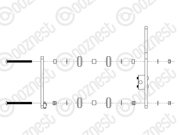
Assemble the bottom right Solid-Wheel set first. Insert a M5-Button-Head-Bolt-60mm through the X-Plate-Front from the front.
-
On to the bolt add an Eccentric-Spacer-6mm. (Rounded portion into the X-Plate-Front)
-
Then add a Precision-Shim - ->- - Solid-Wheel - ->- - Aluminium-Spacer-9mm - ->- - Solid-Wheel - ->- - Precision-Shim
-
Add an Eccentric-Spacer-6mm then the X-Plate-Back. (Rounded portion of the Eccentric-Spacer-6mm goes into the X-Plate-Back)
-
On the outside of the X-Plate-Back add onto the bolt a Precision Shim then a M5-Nyloc-Nut. Only slightly thread on the M5-Nyloc-Nut.
-
Repeat the above for the other Solid-Wheel set on the bottom row.
-
Repeat for the 2 x Solid-Wheel sets on the top row, but use a Aluminium-Spacer-6mm instead of each Eccentric-Spacer-6mm.
-
The M5-Nyloc-Nuts can now be tightened. Ensure that each Solid-Wheel still rotates freely.
-
-
-
On the hexagonal portion of the Eccentric-Spacer-6mm, there will be a face that is marked with ‘6mm’.
-
Using a 8mm spanner, rotate each Eccentric-Spacer-6mm so that this face is facing downwards. (Doing this maximises the gap between the top and bottom row of Solid-Wheels)
-
Insert Extrusion-D in-between the two rows of wheels. Turn the assembly upside down so Extrusion-D is sitting on the top row of Solid-Wheels.
-
Rotate both Eccentric-Spacer-6mms on one set of Solid-Wheels until there is a small amount of friction between the Solid-Wheels and Extrusion-D
-
Repeat for the other set of Solid-Wheels.
-
Slide Extrusion-D back and forth. This should require a small amount of force, and all Solid-Wheels should spin.
-
Check there is no wobbling of Extrusion-D. Once happy, double-check the tightness of the M5-Nyloc Nuts and remove Extrusion-D.
-
Try to get all the Solid-Wheels touching Extrusion-D as best as possible. If not, it is not a problem, we will check the Eccentric-Spacers-6mms again once the machine is built.
-
-
-
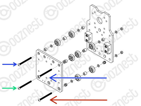
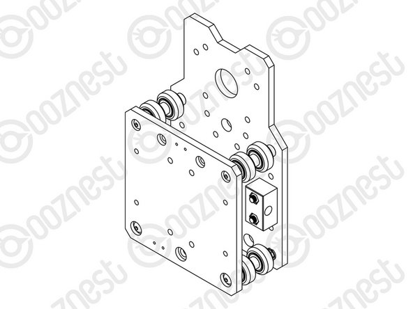
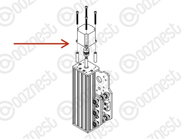
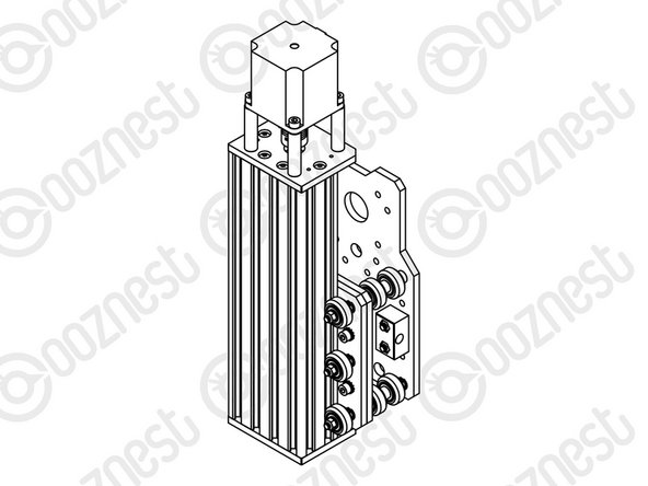
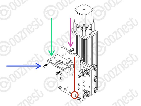
Mate the Z-Plate-Assembly to the X-Plate-Front.
-
The Z-Plate-Assembly should be orientated with the Eccentric-Spacer-6mms on the right side.
-
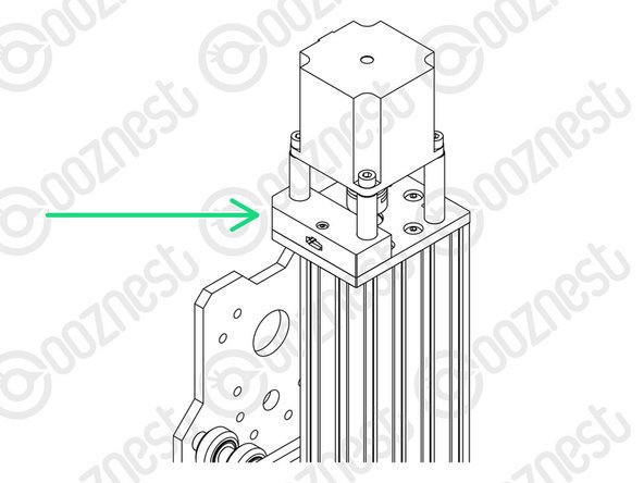
Secure using 4 x M5-Cap-Head-Bolt-12mm, 4 x Precision Shim and 4 x Locking-Washer.
-
The Locking-Washer should go in-between the Precision-Shim and Z-Plate.
-
Make sure the Z-Plate-Assembly is square to the X-Carriage-Assembly.
-
Do not over-tighten the M5-Cap-Head-Bolt. If over-tightened it will reduce the effectiveness of the Locking-Washer.
-
-
-
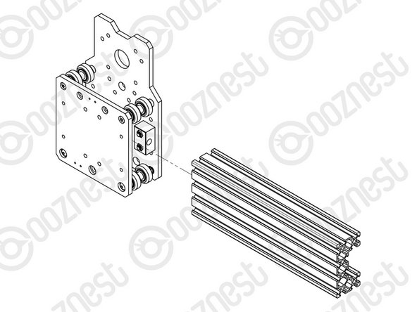
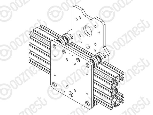
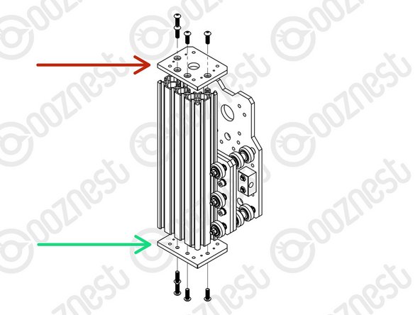
Slide Extrusion-D through the Solid-Wheels on the Z-Plate-Assembly.
-
Attach a Z-End-Plate to the top of Extrusion-D using 4 x M5-Button-Head-Bolt-16mm.
-
Tighten the bolts fully.
-
Attach a Z-End-Plate to the bottom of Extrusion-D using 4 x M5-Button-Head-Bolt-16mm.
-
Tighten the bolts fully, and then loosen by a single full turn.
-
The reason for this will become clear later.
-
-
-
Slide the 1/4” side (the side with the smallest hole) of the Flexible-Coupler onto the shaft of the Stepper-Motor. Don’t tighten it down at this point.
-
Attach the Stepper-Motor to the threaded holes on the top Z-End-Plate using 4 x M5-Cap-Head-Bolt-50mm and 4 x Aluminium-Spacer-40mms.
-
Orient the Stepper-Motor so that the wire is towards the back of the X-Carriage-Assembly.
-
If you have the Touch Probe, follow Step 3 of Assembling Your Original WorkBee XYZ Touch Probe to attach the left side of the Stepper Motor.
-
In this case it should look like Image 3.
-
-
-
Slide the Lead-Screw-Z through the bottom Z-End-Plate. Then slide on a Flanged-Radial-Bearing (facing downwards) - ->- - Bearing-Shim - ->- - Lock-Collar.
-
Thread the Lead-Screw-Z through the Z-Axis-Nut-Block. Then slide on a Lock-Collar - ->- - Bearing-Shim - ->- - Flanged-Radial-Bearing (facing upwards).
-
Continue threading through the Lead-Screw-Z until it is touching the Stepper-Motor shaft.
-
Position the Flexible-Coupler so it is half on the Lead-Screw-Z and half on the Stepper-Motor shaft.
-
On the Stepper-Motor side make sure the Flexible-Coupler grub screw is on the flat portion of the Stepper-Motor shaft. Once in position, on both sides tighten the clamping bolts first, then the grub screws.
-
Top & Bottom, slide the Flanged-Radial-Bearings along the Lead-Screw-Z until they seat fully in the Z-End-Plates.
-
Slide the Bearing-Shim against the Flanged-Radial-Bearing, and finally slide the Lock-Collar so it is firmly against the Bearing-Shim. Lock each Lock-Collar in place using the grub screw on the side.
-
Locate the four bottom M5-Button-Head-Bolt-16mm that were loose from Step 9. These can now be fully tightened. This will remove any play that may be present.
-
-
-
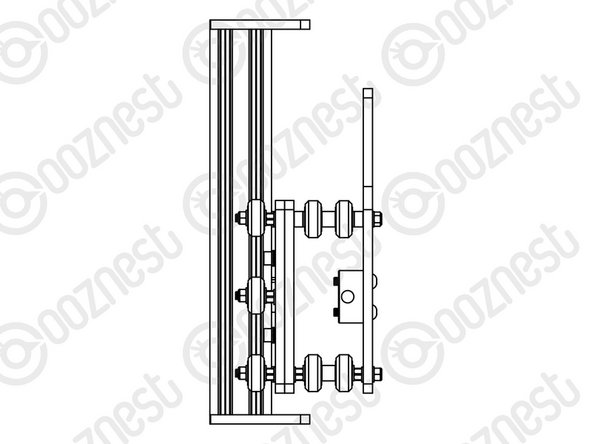
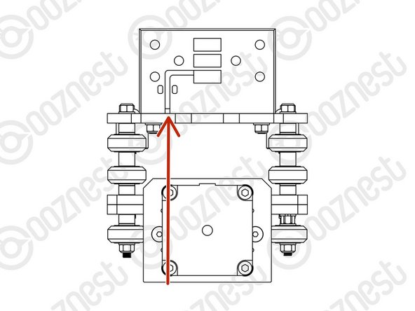
Firmly hold the Assembly, and check for any up and down play in Extrusion-D.
-
If there is any, this is due to backlash in the Z-Axis-Nut-Block.
-
The set screw which was inserted in Step 3 into the Z-Axis-Nut-Block can be tightened to remove backlash.
-
Do not over tighten this, as it can make the Lead-Screw-Z difficult to turn. You can test this by rotating the Flexible-Coupler by hand.
-
It should require a small to medium amount of force. This will need to be checked once the router is attached, and periodically checked when in use.
-
-
-
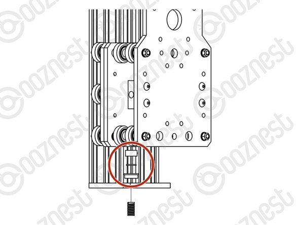
Feed the wire of Limit-Switch-2 attached in Step 5 through the hole opposite on the X-Plate-Back.
-
A Drag-Chain-Mount needs to be attached to the X-Plate-Back.
-
Insert 2 x M5-Button-Head-Bolt-16mms through the Drag-Chain-Mount.
-
Notice on the back of the Drag-Chain-Mount there is a slot. The Limit-Switch-2 wire goes up the X-Plate-Back and through this slot.
-
Put the Drag-Chain-Mount against the X-Plate-Back with the Limit-Switch-2 wire in this slot.
-
Then add a Precision-Shim and M5-Nyloc-Nut on the opposite side of the X-Plate-Back.
-
Tighten the Drag-Chain-Mount against the X-Plate-Back
-
-
-
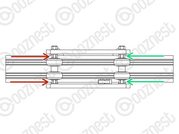
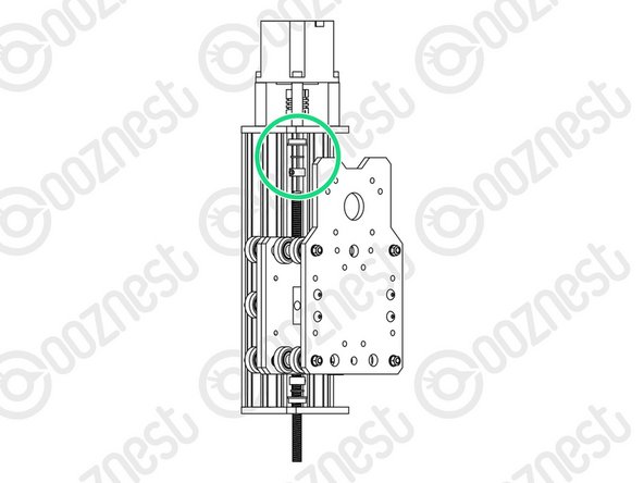
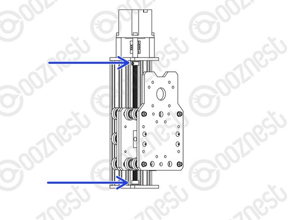
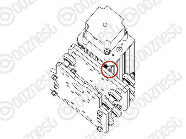
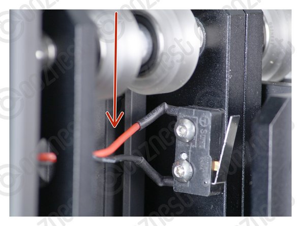
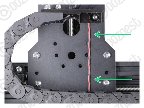
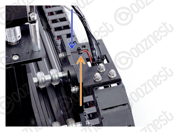
Pull the Limit-Switch-2 Wire taut all the way from the switch to the Drag-Chain-Mount.
-
Image 1 shows it taut in-between the Solid-Wheels.
-
Image 2 shows it taut up the back of the X-Plate-Back.
-
Image 3 shows it inside the slot on the Drag-Chain-Mount.
-
Make sure it is taut the whole way.
-
Use a small cable tie to secure it to the Drag-Chain-Mount.
-
Make sure your Limit-Switch-2 Wire looks exactly like the images.
-
Double Check - Make sure your Limit-Switch-2 Wire looks exactly like the images.
-
-
-
Clear the table, you are going to need room. Keep this X-Carriage with you.
-
Guide Complete - Proceed to 4. X-Gantry Assembly
-


Thanks for following the guide. Any issues, please contact us!
Thanks for following the guide. Any issues, please contact us!
Cancel: I did not complete this guide.
92 other people completed this guide.

7 Comments
This applies through all the guides…it would be useful to start each step with the list of parts needed in the step. We find we have to read the step to find all the parts we need, then read again to see what we need to do now that we can see what the parts look like, then read again when we do the necessary tasks.
Chris McMahon - Resolved on Release Reply
I find that the wheels don’t seem to all locate perfectly in line with the extrusion D. This means a couple don’t make contact when it’s in operation or spin oddly. Doesn’t seem to be making any issues as the other 4 make contact and it travels the Z axis fine, but is there a way of making sure all wheels are located snugly?
Hi George,
Have you tried doing the outer most wheels first, getting them perfect, then just bring the middle ones down onto the extrusion slowly just until touching, but not too much the it effects the outer two.
Robert -