
Introduction
Be very careful to not over tighten the nuts and bolts on the plastic parts, otherwise they
may crack. Everything should easily fit together, and so if it isn’t, take a step back and
re-read the instructions.
-
-
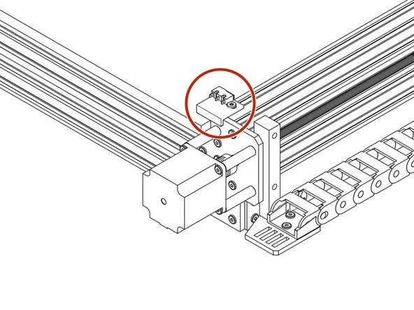
Carefully attach the X-Axis Limit Switch to the X-Axis Limit Switch Mount using 2 x M3 Plastite Screw - 8mm's. The M3 Plastite Screw - 8mm's self thread, the best technique is to screw in a couple of turns, then back out, and then back in a few more turns than last time, and so forth, until the Limit-Switch is firmly secured.
-
Do not over tighten as you can shatter the switch. Make sure the Limit-Switch is orientated as the X-Axis-Limit-Switch-Assembly picture.
-
Attach a M5 Low Profile Bolt - 8mm through the elongated hole and slightly thread on a M5 Drop In Tee Nut.
-
Attach the X-Axis Limit Switch Mount assembly to the back side of the X-Axis C-Beam. It should be oriented as the second picture, on the far left hand side (If looking from the back of the machine). The X-Axis Limit Switch Mount should be touching the Y-Plate.
-
Tighten the M5 Low Profile Bolt - 8mm bolt, engaging the M5 Drop In Tee Nut with the top slot of the X-Axis C-Beam.
-
-
-
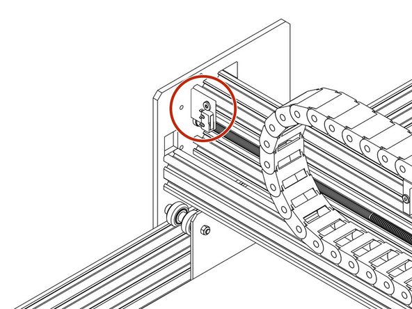
Carefully attach the Y-Axis Limit Switch to the Y-Axis Limit Switch Mount using 2 x M3 Plastite Screw - 8mm's. The M3 Plastite Screw - 8mm's self thread, the best technique is to screw in a couple of turns, then back out, and then back in a few more turns than last time, and so forth, until the Limit-Switch is firmly secured.
-
Do not over tighten as you can shatter the switch. Make sure the Limit-Switch is orientated as the Y-Axis-Limit-Switch-Assembly picture.
-
Attach a M5 Low Profile Bolt - 8mm through the elongated hole and slightly thread on a M5 Drop In Tee Nut.
-
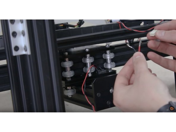
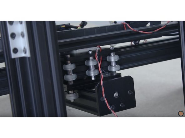
Attach the Y-Axis Limit Switch Mount assembly to the back side of the Right Y-Axis C-Beam (If looking from the back of the machine). It should be oriented as the third picture. The Y-Axis Limit Switch Mount should be touching the Y-C Beam Extrusion.
-
Tighten the M5 Low Profile Bolt - 8mm bolt, engaging the M5 Drop In Tee Nut with the top slot of the Y-Axis C-Beam.
-
-
-
At this stage of the guide review your machine and guide pictures to ensure correct installation.
-
Your finished assemblies should look like the pictures once completed.
-
-
-
Refer to this step for Wire Identifications
-
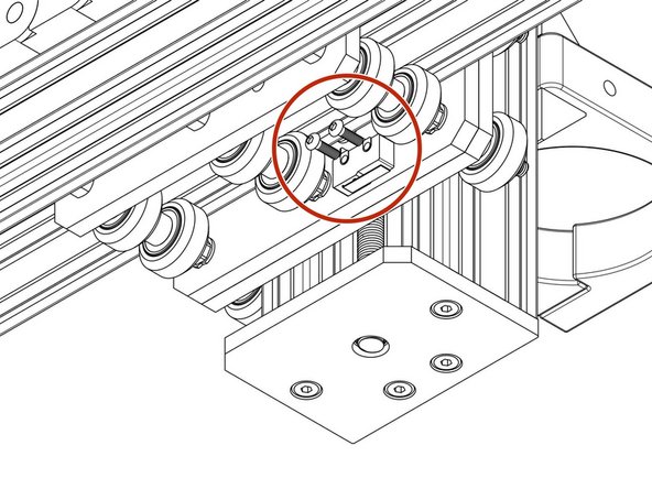
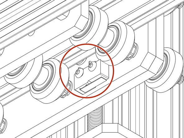
Attach the Z-Axis limit switch to the threaded holes on the X-Plate-Front using 2 x M3- Socket-Head-10mm bolts, in the same orientation as the picture.
-
Do not over tighten as you can shatter the switch. Make sure the Limit-Switch is orientated as the Z-Axis-Limit-Switch-Assembly picture.
-
-
-
Insert wisdom here.
-


Thanks for following the guide. Any issues, please contact us!
Thanks for following the guide. Any issues, please contact us!
Cancel: I did not complete this guide.
28 other people completed this guide.
