
-
-
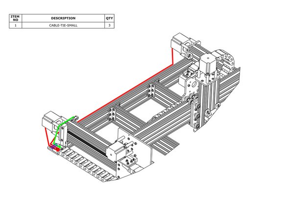
The Z-Limit-Switch sits in-between two sets of wheels. Directly opposite there is a hole. Feed the wires through this hole (red circle).
-
Pull the wire tight to prevent the wire rubbing on the C-Beam Extrusion.
-
As shown by the green line above bring the Z-Limit-Switch wires up the X-Plate-Back, and feed it through the X-Drag-Chain.
-
Secure the wires using Cable-Tie-Smalls to the points marked with blue circles. To stop it snagging on anything the wire should be pulled tight.
-
-
-
For the Z-Axis Motor Wire that is inside the X-Drag-Chain, connect it to the pigtail on Z-Axis stepper motor. Making sure there is enough slack for the full travel of the Z-Axis shown in red, secure the wire to the X-Drag-Moving-End-Mount using a Cable-Tie-Small, shown by the small blue circle above.
-
The lead on the X-Axis limit switch should be secured to the V-Slot-2040-750mm using a Cable-Tie-Large at the position shown by the blue oval above. Then run the lead along to the other end of V-Slot-2040-750mm - it can be tucked into one of the slots.
-
-
-
Connect the two stepper motor wires in the Y-Drag-Chain to their corresponding pigtails on the Y-Axis stepper motors. The longer wire should connect to the right hand stepper motor.
-
Secure the stepper motor wires to the Y-Axis-Fixed-End-Mount using Cable-Tie Smalls. The wire for the right hand stepper motor can be tucked into a slot on one of the extrusions along the back.
-
Secure the lead on the Y-Axis limit switch to the Y-Axis-Fixed-End-Mount using a Cable-Tie-Small.
-
-
-
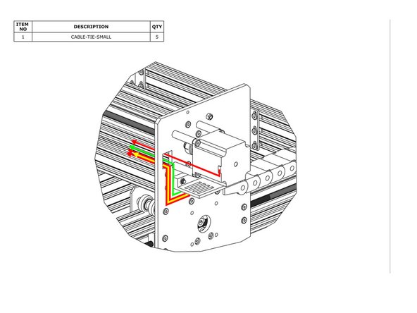
Connect the X-Axis motor wire to the pigtail on the X-Axis stepper motor and feed it through the square hole on the Y-Plate.
-
Inside the Y-Drag-Chain there should be two stepper motor wires (red line), a power supply wire (yellow line), and a limit switch wire (green line). Feed all of these through the square hole on the Y-Plate.
-
Remove any slack inside the Y-Drag Chain, and then secure these 4 wires to the Y-Drag-Chain-Moving-End-Mount using Cable-Tie-Smalls.
-


Thanks for following the guide. Any issues, please contact us!
Thanks for following the guide. Any issues, please contact us!
Cancel: I did not complete this guide.
37 other people completed this guide.