
-
-
Version Check: Only follow this guide if you have a V2.3.1 WorkBee. The version number of your machine can be found on the WorkBee Flyer.
-
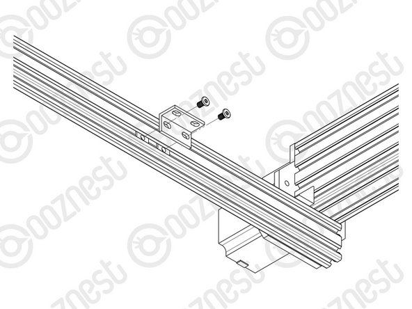
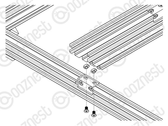
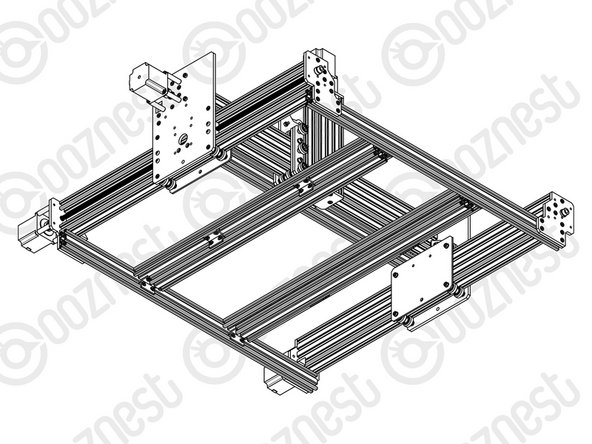
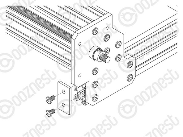
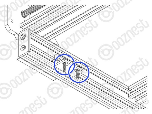
Attach one side of an Angle Corner to the inside face of the right hand C-Beam using a M5-Low-Profile-8mm bolt and a M5-Drop-In-Tee-Nut. Attach the other side to the V-Slot-2040 using a M5-Low-Profile-8mm bolt and a Tee-Nut that can be inserted from the end of the V-Slot-2040.
-
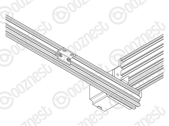
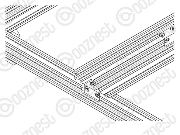
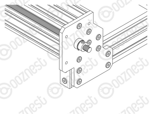
Secure the Angle-Corner tightly in the corner between the C-Beam and V-Slot-2040 while the machine is held square.
-
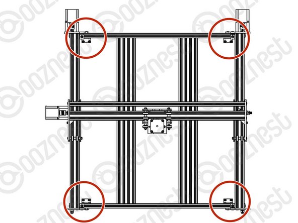
Repeat for the other 3 corner joints between the C-Beam and V-Slot 2040 rails.
-
-
-
If you have a machine with an X-Axis larger than 750mm only two spoiler board supports touch the workbench. The others span from front to back.
-
We recommend placing the spoiler board supports in the following configurations:
-
750mm or Smaller X-Axis
-
Supported - Supported
-
1000mm X-Axis
-
Supported - Unsupported - Supported
-
1500mm X-Axis
-
Supported - Unsupported - Unsupported - Supported
-
-
-
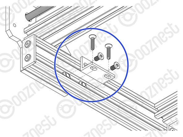
With a Universal-Bracket-Double in hand, notice that the holes down one side are not the same distance away from the corner edge as the holes on the other side. The side with the holes closest to the corner edge should go against the V-Slot-2040.
-
Each Spoiler Board Support outlined in Step 2, requires a Universal-L-Bracket-Double at the front and back of the machine.
-
Space the centre of the brackets from the edge of the V-Slot-2040 and then centre to centre as follows:
-
750mm X-Axis: Edge - 248mm, Centres - 248mm.
-
1000mm X-Axis: Edge - 249mm, Centres - 249mm.
-
1500mm X-Axis: Edge - 299mm, Centres - 299mm.
-
For each bracket insert 2 x Tee-Nuts into the bottom slot of the V-Slot-2040 and secure it using 2 x M5-Low-Profile-8mm’s With the bottom edge of the Universal-Bracket-Double flush with the bottom of the V-Slot-2040.
-
The above spacings are our recommendations for general use. But can be changed for specific use cases.
-
-
-
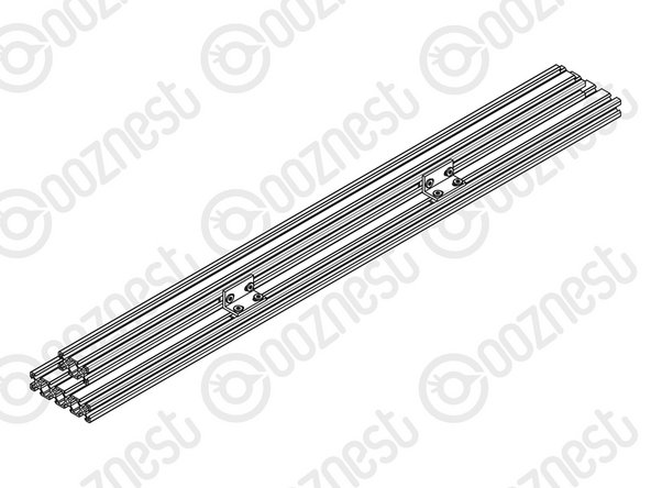
This step only needs to be carried out twice for all X-Axis sizes.
-
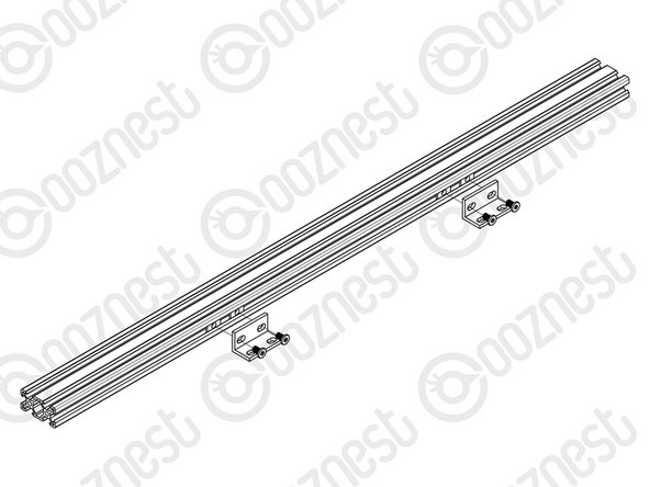
Insert 4 x Tee-Nuts into the right facing slot of the V-Slot-2040-665mm.
-
With a Universal-Bracket-Double in hand, notice that the holes down one side are not the same distance away from the corner edge as the holes on the other side. The side with the holes closest to the corner edge should go against the V-Slot-2040-665mm.
-
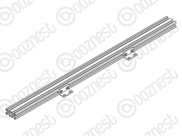
With the bottom edge of the Universal-Bracket-Double flush with the bottom of the V-Slot-2040-665mm, secure it using 2 x M5-Low-Profile-8mm’s. There should be 180mm between the Universal-Bracket-Double and the end of the V-Slot-2040-665mm.
-
Attach another Universal-Bracket-Double, 180mm away from the other end.
-
-
-
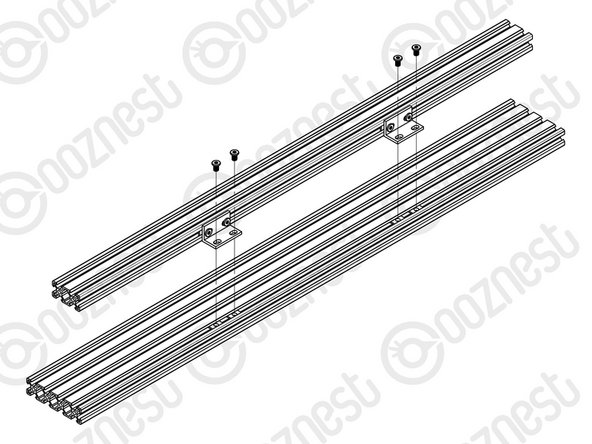
This step only needs to be carried out twice for all X-Axis sizes.
-
Insert 4 x Tee-Nuts into the furthest left bottom facing slot of the V-Slot-2080- 710mm.
-
Attach the other side of the Universal-Bracket-Doubles in Step 3 along with the V-Slot 2040-665mm to the V-Slot-2080-710mm using 4 x M5-Low-Profile-8mm’s.
-
Center the V-Slot-2040-665mm on the V-Slot-2080-710mm extrusion
-
Repeat Step 4 and the above for the other V-Slot-2040-665mm and V-Slot-2080-710mm.
-
-
-
To complete the follow steps either prop the machine up on the end you are working on, or hang the side of the machine over the edge of a table.
-
Through the two holes on each Universal-Bracket-Double, attach a M5-Low-Profile-8mm bolt and slightly thread on a M5-Drop-In-Tee-Nut.
-
Bring the Spoiler-Board-Support-Assemblies down onto the two Supported sets of Universal-Bracket-Double as outlined in Step 2.
-
Centre the V-Slot-2080 flush with the outside edge of the Universal-Bracket-Double.
-
Align the M5-Drop-In-Tee-Nuts with the slots. Tighten the M5- Low-Profile-8mm’s to secure the Spoiler-Board-Support-Assemblies.
-
If you have a 750mm X-Axis or smaller, the assemblies made in Steps 4 and 5 will take up all Universal-L-Bracket-Double attached to the machine in Step 3.
-
1000mm X-Axis there will be one set of Universal-Bracket-Doubles left empty, attach the left-over V-Slot-2080 to this set.
-
1500mm X-Axis there will be two sets of Universal-Bracket-Doubles left empty, attach the two left over V-Slot-2080’s to these sets.
-
-
-
Attach an End-Cap to the front left end of the V-Slot-2040 using 2 x M5-Low-Profile-8mm bolts.
-
Repeat this for the other 3 x End-Caps on the other bare ends of the V-Slot-2040.
-
-
-
Make sure your WorkBee CNC Machine is placed on a flat and level surface.
-
The Screws referenced in this step are not provided.
-
Insert 2 x Drop-in Tee-Nuts into the bottom slot of the V-Slot-2040.
-
With a Universal-Bracket-Double in hand, notice that the holes down one side are not the same distance away from the corner edge as the holes on the other side. The side with the holes closest to the corner edge should go against the V-Slot-2040, 50mm away from the End-Cap.
-
With the bottom edge of the Universal-Bracket-Double flush with the V-Slot-2040, secure it using 2 x M5-Low-Profile-8mm’s and the Drop-In-Tee-nuts inserted previously.
-
The Universal-Bracket-Double can now be secured to your table using a general purpose wood screws.
-
Repeat for the other three corners.
-


Thanks for following the guide. Any issues, please contact us!
Thanks for following the guide. Any issues, please contact us!
Cancel: I did not complete this guide.
23 other people completed this guide.
