
-
-
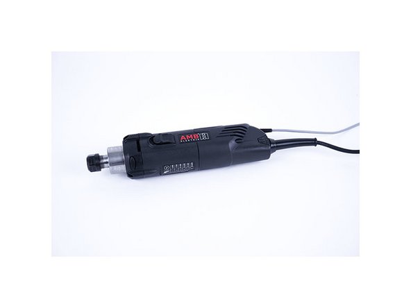
AMB Kress or Mafell spindle with digital control
-
PWM to voltage 0-10V converter (see links)
-
Small wiring cables suitable for 24V
-
-
-
'Disconnect the power supply of the duet controller first!'
-
PWM converter has 4 inputs (2 power + 2 pwm input signals) and 2 outputs (0-10V voltage). Make sure the yellow jumper is on the 24V pins as we are using the duet pwm signal output which is 12/24V.
-
Power wiring to the PWM converter
-
Connect the “VIN” power pin on the duet board (see image) to port 3 on the pwm converter “power supply + (12-30V)”
-
Connect the “GND” power pin on the duet board to port 4 on the pwm converter “power supply – (GND)”
-
Pwm signal wiring to the pwm converter using HEATER E0 of the duet board
-
Connect “VIN” from heater E0 to port 2 “PWM input + (din+)” on the pwm converter
-
Connect “E0-” from heater E0 to port 1 “PWM input – (DIN-)” on the pwm converter
-
-
-
Other than the power supply cable 110V/220V, the spindle has 3 small cables:
-
BROWN 10-26V DC (for power supply)
-
GREEN 0-10V DC (for speed control)
-
WHITE 0 V (for ground/GND)
-
-
-
Brown to “VIN” connector of the duet power supply pin
-
Green to port 6 “voltage output + (AO)” of the pwm converter
-
White to port 5 “ voltage output – (GND)” of the pwm converter
-
Connect port 5 “ voltage output – (GND)” of the pwm converter to the “GND” pin of the power supply on the duet board
-
THE LAST STEP (port 5 to GND pin duet) IS REALLY IMPORTANT! You create a common ground between the spindle and pwm converter/power supply
-
-
-
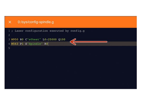
Under File Management > System click on 'config-spindle.g'. Then add the following lines
-
M950 R0 C"e0heat" L0:25000 Q100
-
L is the minimum and maximum RPM of your Spindle. Adjust accordingly.
-
Q is the frequency. If your spindle keeps fluctuating at lower rpms, change the frequency to 300. If it still keeps fluctuating, change it to 320 or 350 and so on.
-
M563 P1 S"Spindle" R0
-
Press the software emergency stop in the top right corner to restart the controller.
-
-
-
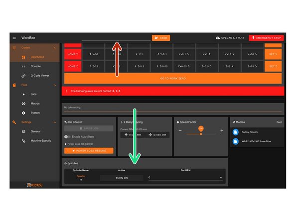
You can control the spindle manually using G-Code.
-
For example M3 S25000, turns the spindle on clockwise and sets the spindle speed at 25000rpm
-
M5 Stops the Spindle.
-
You can also control it in the 'Spindles' panel.
-
Press 'Turn On' will turn the spindle on clockwise at the RPM set.
-
You can change the preset RPMs under Settings > Machine Specific > Spindle RPM Presets.
-
If you have a multimeter, try to read the output voltage of the pwm converter (port 5 and 6). If it says 10V, you are on the maximum spindle speed.
-
You can also add a digital led voltmeter on port 5 and 6 of the pwm controller (see image 2)
-
-
-
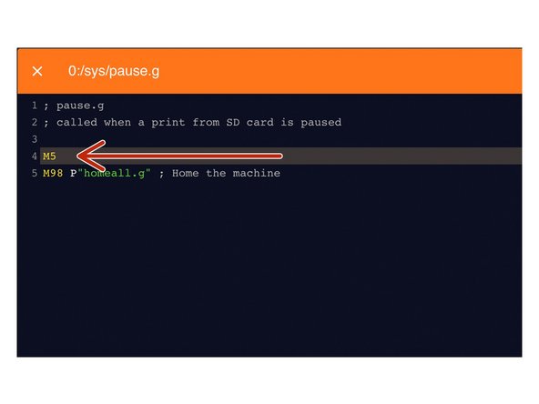
Under File Management > System click on 'pause.g'.
-
Add the command M5 in the header, so the spindle stops when you pause a job while running
-
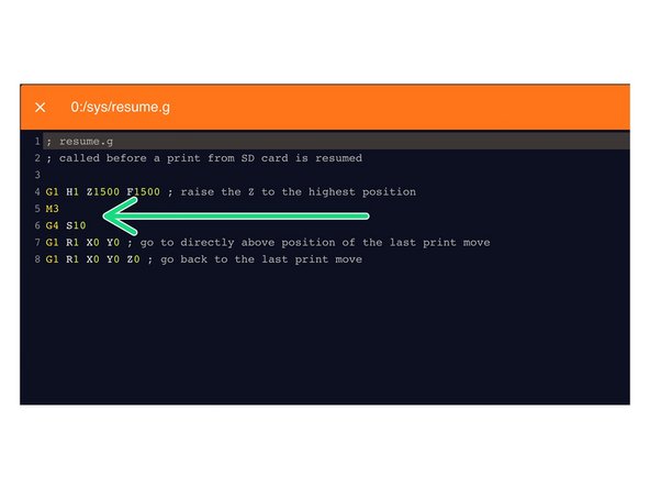
Open the resume.g file and add the following lines
-
M3
-
The Spindle RPM is not needed. It will go back to the RPM when the M5 command was sent.
-
G4 S10
-
Dwell for 10 seconds to let the Spindle get up to speed.
-
-
-
Modify the vectric's post processor to autmatically use spindle speed.
-
Go to the installation directory of the Vectric software, search for “grbl_mm.pp” and make a copy in the same directory and open the copy
-
Change the POST_NAME to something else, I did “GRBL (mm) (SPEED)
-
In the header, change “M3” to “M3[S]” to add speed to the M3 command
-
After your "M3[S]" line, add a new line "G4S15". This code tells the machine to wait 15 seconds to achieve full spindle speed before starting a job
-
Save your file in the post processor directory, make sure it ends with .pp or Vectric does not recognise it!
-
Next time you open the Vectric software, your new post processor will be added to the PP list
-
-
-
Many many thanks to user “Tubal” from the Openbuilds forum, who describes part of the process Openbuilds forum link
-
PWM converter Amazon link
-
Power wiring diagram Duet power wiring
-
AMB Kress wiring diagram from SOROTEC PDF wiring diagram
-
Duet 2 G codes overview Reprap Gcode overview
-


Thanks for following the guide. Any issues, please contact us!
Thanks for following the guide. Any issues, please contact us!
Cancel: I did not complete this guide.
5 other people completed this guide.
21 Comments
Hello, I have tried to set this up with the Mafell 1000 PV-ER. The problem is, that spindle never stops completely when clicking spindle off.
I can turn on and adjust the speeds on the screen but selecting off just slows the spindle but never off.
Any ideas? Thanks.
With "Connect port 5 “ voltage output – (GND)” of the pwm converter to the “GND” pin of the power supply on the duet board"
Isn't this just connecting Port 5 of the PWM to Port 4 (which is already connected to the GRN of the Duet)?
Hi . step 8- how do i do this using the carveco software ?
thanks
Chris I have implemented this on a Mafell thanks for you hard work on this. Unfortunately it does not respond to the M3 or M5 Gcodes. The speed setting works fine. I am presuming this is a limitation of the Mafell. Or does anybody else know anything different? Or could it be I set the range as specified in the manual like this : M950 R0 C"e0heat" L4000:25000 Q100
Sorry that should have does not switch off with M5 . M3 commands with speed works fine.