
-
-
You are going to need our Motor Wire and Limit Switch Cheat Sheet. We recommend printing it off!
-
-
-
Make sure your power supply is switched off.
-
Connect the output wire of the Emergency-Stop into the input screw terminal on the Controller.
-
Use an Insulated Flathead Screwdriver.
-
-
-
The connectors on the wires are keyed, so there is only one way which they can plug in.
-
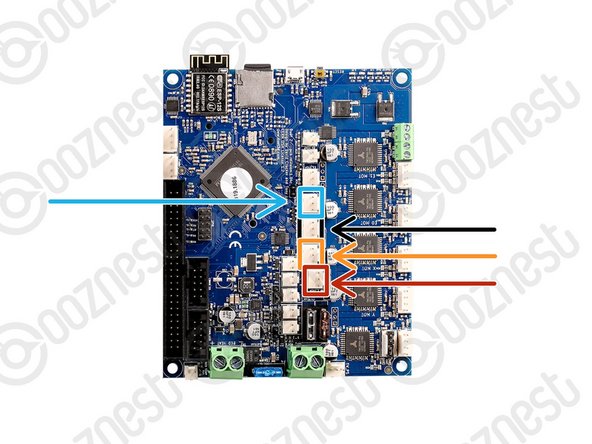
Plug in the limit switch wires following Image 1.
-
Limit-Switch-0 (X-Axis)
-
Limit-Switch-1 (Y-Axis)
-
Limit-Switch-2 (Z-Axis)
-
The Touch Probe wire can also be plugged in.
-
-
-
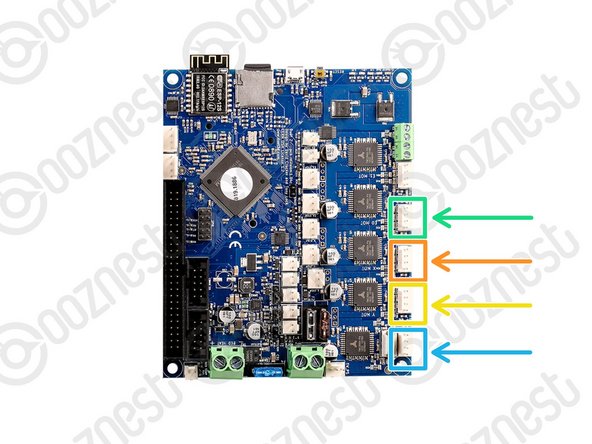
Plug in the motor wires following Image 1.
-
Motor-Wire-5 (Y-Axis-Right)
-
Motor-Wire-3 (X-Axis)
-
Motor-Wire-4 (Y-Axis-Left)
-
Motor-Wire-6 (Z-Axis)
-
-
-
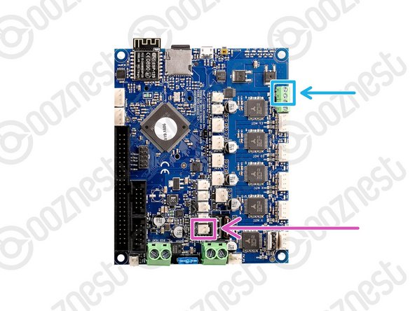
Plug the Controller-Fans into the Controller following Image 1.
-
Plug the LED Light Ring into the Controller following Image 1. Follow this full guide How To Connect LED Light Ring
-


Thanks for following the guide. Any issues, please contact us!
Thanks for following the guide. Any issues, please contact us!
Cancel: I did not complete this guide.
10 other people completed this guide.
