
-
-
If the wires in your kit have white printed tags, please ignore this step. Each wire, at the connector end has a coloured clip with a number. This colour and number identifies this wire. Please see key below.
-
(0)(Black) X-Axis Limit Switch
-
(1)(Brown) Y-Axis Limit Switch
-
(2)(Red) Z-Axis Limit Switch
-
(3)(Orange) X-Axis Stepper Motor Wire.
-
(4)(Yellow) Left Y-Axis Stepper Motor Wire.
-
(5)(Green) Right Y-Axis Stepper Motor Wire.
-
(6)(Light Blue) Z-Axis Stepper Motor Wire.
-
-
-
It is normally easier to connect the female end of the Y-Drag-Chain to a Drag-Chain-Fixed-End now, and then proceeding with the guide.
-
It will take some force to click the Y-Drag-Chain into the Drag-Chain-Fixed-End. A small flathead screwdriver can be used to help pry the Y-Drag-Chain in place.
-
Attach the Drag-Chain-Fixed-End to the Y-Drag-Chain-Fixed-End-Mount in the orientation shown above, using 3 x M5-Low-Profile-15mm bolts and 3 x M5-Nyloc-Nuts.
-
Attach a Drag-Chain-Fixed-End to the Y-Drag-Chain-Fixed-End-Mount in the orientation shown above, using 2 x M5-Low-Profile-15mm bolts and 2 x M5-Nyloc-Nuts.
-
-
-
Position the Y-Axis-Fixed-End-Assembly to the back left corner of the WorkBee.
-
It should be flush with the end of the C-Beam-750mm. Secure it using 2 x M5-Low-Profile-25mm bolts and 2 x M5-Drop-In-Tee-Nuts.
-
-
-
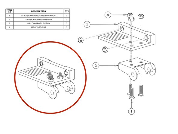
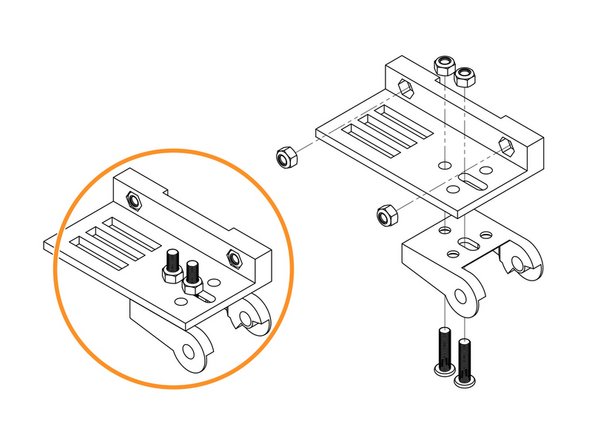
Insert 2 x M5-Nyloc-Nuts into the insets on the Y-Drag-Chain-Moving-End-Mount. They are a snug fit, so may require a light tap with a hammer.
-
Attach a Drag-Chain-Moving-End to the Y-Drag-Chain-Moving-End-Mount in the orientation shown above using 3 x M5-Low-Profile-15mm bolts and 3 x M5-Nyloc-Nuts.
-
Attach a Drag-Chain-Moving-End to the Y-Drag-Chain-Moving-End-Mount in the orientation shown above using 2 x M5-Low-Profile-15mm bolts and 2 x M5-Nyloc-Nuts.
-
-
-
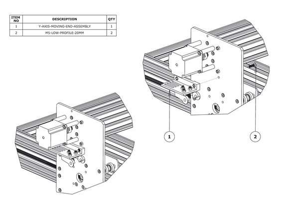
Secure the Y-Axis-Moving-End-Assembly using 2 x M5-Low-Profile-15mm bolts and the 2 x M5-Nyloc-Nuts already inserted into Y-Drag-Chain-Moving-End-Mount.
-
-
-
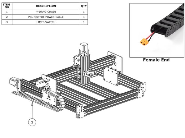
Lay the Y-Drag-Chain flat on a table. Feed the PSU-Output-Power-Cable through the whole length of the Y-Drag-Chain. Ensure that the end with the XT60-Connector, is located at the female end of the Y-Drag-Chain. (as shown in the ‘Female End’ image).
-
Feed the two (4)(Yellow) & (5)(Green) Y-Axis Stepper Motor Wires through the Y Drag-Chain. The end of the stepper motor wires with the black connector should be at the female end of the Y-Drag-Chain - same as above.
-
Feed the wires on the (1)(Brown) Y-Axis Limit-Switch, through the Y Drag-Chain. The switch portion of the Limit-Switch should be at the female end of the Y-Drag-Chain.
-
If you have the Ethernet version of the Duet, now would be a good time to also insert this wire.
-
The tabs of the Drag-Chain can be flipped open with a small flathead screwdriver. Doing this will help to feed the cables.
-
Lay the Y-Drag-Chain flat along the left side of the WorkBee. The female end of the Y-Drag-Chain should be at the back of the machine, and the male end at the front.
-
Attach the female end of the Y-Drag-Chain to the Drag-Chain-Fixed-End on the Y-Axis Fixed-End-Assembly. It will take some force to click it into the Drag-Chain-Fixed-End. A small flathead screwdriver can be used to help pry the Drag-Chain in place.
-
Bring the male end of the Y-Drag-Chain to the Y-Axis-Moving-End-Assembly and attach it to the Drag-Chain-Moving-End. It will take some force to click it into the Drag-Chain-Moving-End. A small flathead screwdriver can be used to help pry the Drag-Chain in place.
-


Thanks for following the guide. Any issues, please contact us!
Thanks for following the guide. Any issues, please contact us!
Cancel: I did not complete this guide.
36 other people completed this guide.
One Comment
I'm struggling to identify which drag chain is which as mine are unlabeled I am assuming that the longer one is the y axis .
Nathan Hopkins - Resolved on Release Reply