
-
-
If the wires in your kit have white printed tags, please ignore this step. Each wire, at the connector end has a coloured clip with a number. This colour and number identifies this wire. Please see key below.
-
(0)(Black) X-Axis Limit Switch
-
(1)(Brown) Y-Axis Limit Switch
-
(2)(Red) Z-Axis Limit Switch
-
(3)(Orange) X-Axis Stepper Motor Wire.
-
(4)(Yellow) Left Y-Axis Stepper Motor Wire.
-
(5)(Green) Right Y-Axis Stepper Motor Wire.
-
(6)(Light Blue) Z-Axis Stepper Motor Wire.
-
-
-
Attach a Drag-Chain-Fixed-End to the V-Slot-2040-750mm using an M5-Low-Profile 8mm and an M5-Drop-In-Tee-Nut.
-
It should be located 150mm from right hand end of the V-Slot-2040-750mm if looking from the back. Ensure that it is parallel with the V-Slot-2040-750mm.
-
-
-
WorkBee Kits may include different version drag chains, please refer to the correct drawings for assembly of the version supplied.
-
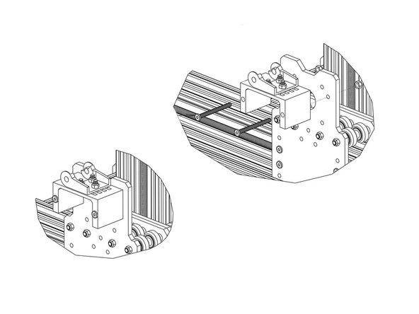
Attach a Drag-Chain-Moving-End to the X-Drag-Chain-Moving-End-Mount in the orientation shown above using 3 x M5-Low-Profile-15mm bolts and 3 x M5-Nyloc-Nuts.
-
Attach a Drag-Chain-Moving-End to the X-Drag-Chain-Moving-End-Mount in the orientation shown above using 2 x M5-Low-Profile-15mm bolts and 2 x M5-Nyloc-Nuts.
-
-
-
Secure the X-Axis-Moving-End-Assembly to the X-Plate-Back using 2 x M5-Low-Profile-60mm bolts and 2 x M5-Nyloc-Nuts.
-
-
-
Like with the Y-Axis, lay the X-Drag-Chain flat on a table. Feed through the (6)(Light Blue) Z-Axis Stepper Motor Wire.
-
If you have an Ooznest XYZ Touch Probe, please complete Step 4 of Assembling Your Original WorkBee XYZ Touch Probe
-
The tabs of the Drag-Chain can be flipped open with a small flathead screwdriver. Doing this will help to feed the cables.
-
The end of the stepper motor wires with the black connectors should be at the male end of the X-Drag-Chain (opposite to Y-Axis).
-
Attach the female end of the X-Drag-Chain to the Drag-Chain-Fixed-End on the V Slot-2040-750mm. It will take some force to click it into the Drag-Chain-Fixed-End. A small flathead screwdriver can be used to help pry the Drag-Chain in place.
-
Bring the male end of the X-Drag-Chain up to the X-Axis-Moving-End-Assembly and attach it to the Drag-Chain-Moving-End. It will take some force to click it into the Drag-Chain-Moving-End. A small flathead screwdriver can be used to help pry the Drag-Chain in place.
-


Thanks for following the guide. Any issues, please contact us!
Thanks for following the guide. Any issues, please contact us!
Cancel: I did not complete this guide.
36 other people completed this guide.