
-
-
With the Y-Plate-Left in the orientation seen in the picture, insert 2 x M5-Low-Profile-25mm Bolts from the back side through the only two holes that are inset.
-
Next to each M5-Low-Profile-25mm bolt, you can see that there is a non-inset hole. From the front, insert a M5-Low-Profile-20mm Bolt through each of these holes.
-
These M5-Low-Profile-20mm Bolts will be used in the next section to attach the NEMA23-Stepper-Motor.
-
On to each M5-Low-Profile-25mm bolt, place 1 x Aluminium-Spacer-6mm, 2 x Mini-V-Precision-Shims, 1 x Mini-V-Wheel-Assembly and a 1 x M5-Nyloc-Nut in this order. Tighten the whole assembly; insure that the Mini-V-Wheels still spin freely.
-
-
-
Attach a NEMA23-Stepper-Motor to the Y-Plate-Left using 4 x M5-Low-Profile-20mm Bolts (two should have been already inserted in Step 1) and 4 x M5-Nyloc-Nuts. Make sure you place an Aluminium-Spacer-3mm in-between the NEMA23-Stepper Motor and the Y-Plate-Left on each M5-Low-Profile-20mm Bolt.
-
The NEMA23-Stepper-Motor should be orientated so that the wire side is facing towards the back of the Y Plate-Left (the side closest to the small rectangle opening).
-
Attach a GT3-Pulley to the NEMA23-Stepper-Motor shaft using 2 x M3-Cap-Head 4mm Bolts. One of these bolts should be tightened on to the flat portion of the NEMA23-Stepper-Motor shaft. The toothed section of the GT3-Pulley should be centralized to the Mini-V-Wheel-Assembly’s attached in Step 1.
-
-
-
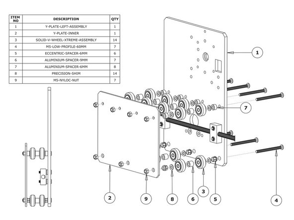
First attach the bottom right wheel set; insert a M5-Low-Profile-60mm bolt through the Y-Plate-Left-Assembly from the back. On to this bolt, add an Eccentric-Spacer 6mm, Precision-Shim, Solid-V-Wheel-Xtreme-Assembly, Aluminium Spacer-9mm, Solid-V-Wheel-Xtreme-Assembly, Precision Shim, and a Eccentric-Spacer-6mm in this order.
-
Next, add a Y-Plate-Inner onto the top of this assemblage, and then slightly thread on a M5-Nyloc-Nut. The rounded portion of the Eccentric-Spacer-6mm should be inserted into the hole on either the Y-Plate-Left-Assembly or Y-Plate-Inner (depending on which side it is on).
-
Repeat for the other two wheel sets on the bottom row.
-
Repeat for the 4 wheel sets on the top row, however for these sets use Aluminium-Spacer-6mms instead of Eccentric-Spacer-6mms.
-
Once all of the wheels are attached the M5-Nyloc-Nuts can be tightened down. Ensure that the Solid-V-Xtreme-Wheels can still rotate freely. On the hexagonal portion of the Eccentric-Spacer-6mm, there will be one face that is marked with ‘6mm’.
-
Using a spanner, adjust each Eccentric-Spacer-6mm so that this face is facing downwards. Doing this maximizes the gap between the top and bottom row of wheels.
-
-
-
Run any piece of C-Beam extrusion in between the two rows of wheels. Initially, the C-Beam will wobble between the wheels. Turn the assembly upside down so the C-Beam is sitting on the row of wheels with the Aluminium-Spacer-6mms.
-
Starting with an outside pair of wheels, adjust both Eccentric-Spacer-6mms down onto the C-Beam Extrusion until there is a small amount of friction between both wheels and the C-Beam Extrusion.
-
When adjusting the pair of Eccentric-Spacer-6mms ideally they should be adjusted identically. However, sometimes one will need to be adjusted slightly more than the other to get both wheels engaged with the C-Beam extrusion.
-
Repeat for the other outside pair of wheels, and then again for the middle pair.
-
Slide the C-Beam extrusion back and forth through the wheels. This should require a small amount of force, and all wheels should spin as it rolls. Also check there is no wobbling of the extrusion. Once happy, double check the tightness of the M5-Nyloc Nuts.
-
-
-
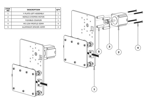
Slide the 1/4” side (the side with the smallest hole) of the Flexible-Coupler onto the shaft of the NEMA23-Stepper-Motor. Don’t tighten it down at this point.
-
Attach the NEMA23-Stepper-Motor to the threaded holes on the Y-Plate-Left using 4 x M5-Low-Profile-50mm bolts and 4 x Aluminium-Spacer-40mm’s.
-
Orient the NEMA23- Stepper-Motor so that the wire is towards the back of the Y-Plate-Left (the side closet to the small rectangle opening).
-
-
-
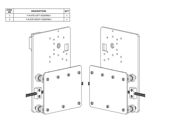
Repeat Steps 1-4 for the Y-Plate-Right. As seen above, it should be a mirror image of the Y-Plate-Left-Assembly.
-
Do not repeat Step 5
-


Thanks for following the guide. Any issues, please contact us!
Thanks for following the guide. Any issues, please contact us!
Cancel: I did not complete this guide.
One other person completed this guide.