
-
-
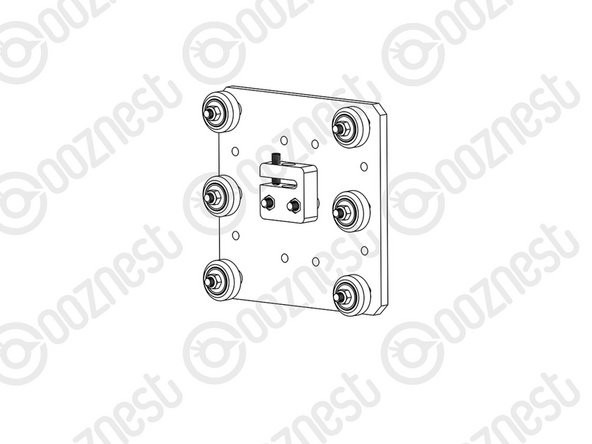
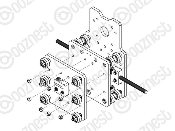
First attach the top right wheel, insert a M5-Low-Profile-30mm through the Z-Plate from the back (the back is the side with the insets). On to this, add an Eccentric Spacer-6mm, Precision-Shim, Solid-V-Wheel-Xtreme-Assembly and a M5-Nyloc-Nut in this order.
-
The rounded portion of the Eccentric-Spacer-6mm should be inserted into the hole on the Z-Plate. The assembly can be tightened, ensuring the Solid-V-Xtreme Wheel can still rotate freely.
-
Repeat the other two wheels on the right row.
-
Repeat for the 3 wheel sets on the left row, however for these sets use Aluminium-Spacer-6mms instead of Eccentric-Spacer-6mms.
-
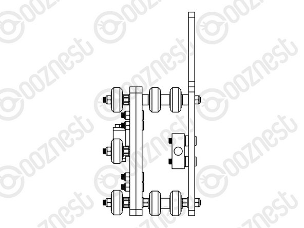
On the hexagonal portion of the Eccentric-Spacer-6mm, there will be one face that is marked with ‘6mm’. Using a spanner, adjust each Eccentric-Spacer-6mm so that this face is facing to the right. Doing this maximizes the gap between the left and right row of wheels.
-
-
-
Run any piece of C-Beam extrusion in-between the two rows of wheels. Initially, there may be a small amount of play between the C-Beam and wheels. Turn the assembly so the C-Beam is sitting on the row of wheels with the Aluminium-Spacer-6mms.
-
Starting with an outside wheel, adjust the Eccentric-Spacer-6mm down onto the C-Beam Extrusion until there is a small amount of friction between the wheel and the C-Beam Extrusion. Repeat this for the other outside wheel, and then for the middle wheel.
-
Repeat this for the other outside wheel, and then for the middle wheel.
-
Slide the C-Beam extrusion back and forth through the wheels. This should require a small amount of force, and all wheels should spin as it rolls. Also, check there is no wobbling of the extrusion. Once happy, double check the tightness of the M5-Nyloc Nuts.
-
-
-
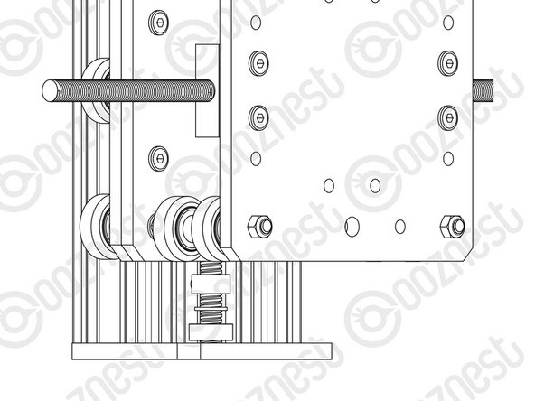
Attach the ACME-AB-Nut-Block to the Z-Plate using 2 x M5-Low-Profile-25mm bolts. In-between the ACME-AB-Nut-Block and Z-Plate on each bolt there should be an Aluminium-Spacer-3mm and a Precision-Shim.
-
With the set screw provided with the ACME-AB-Nut-Block, screw it into the smaller threaded hole on the top until it is just before the point of touching the surface on the opposite side of the gap. The set screw will later be used to remove any back lash from the system.
-
-
-
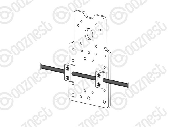
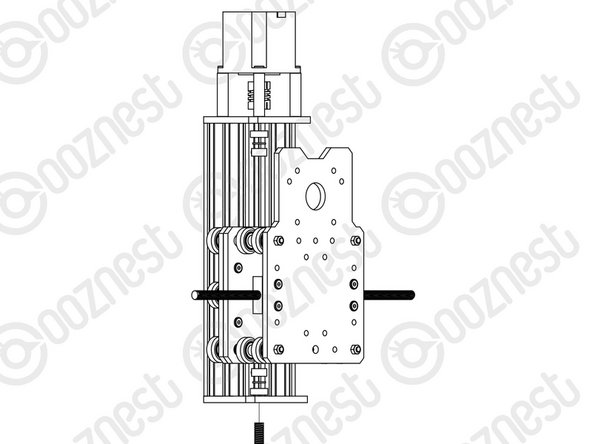
Attach 2 x ACME-Nut-Blocks to the X-Plate-Back using 4 x M5-Low-Profile-25mm bolts & 4 x M5-Nyloc-Nuts. On each bolt, in-between the ACME-Nut-Block and X-Plate-Back, there should be an Aluminium-Spacer-3mm and a Precision-Shim. Only loosely tighten these bolts so the ACME-Nut-Blocks can still move side to side.
-
Thread the X-ACME-Lead-Screw through both ACME-Nut-Blocks. Tighten the bolts holding one of the ACME-Nut-Blocks, making sure it is square to the X-Plate-Back.
-
To remove any backlash, pinch the loose ACME-Nut-Block towards the previous one, and tighten the bolts holding it. Leave the X-ACME-Lead-Screw threaded through the ACME-Nut-Blocks.
-
-
-
If you have the full kit version of the WorkBee, now would be a good time to complete Step 5 on this guide: 4. Limit Switch Assembly & Mounting.
-
Access to the threaded holes is much easier now before the plate is assembled.
-
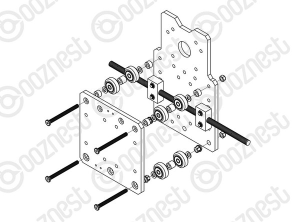
First attach the bottom right wheel set - insert a M5-Low-Profile-60mm bolt through the X-Plate-Front through the side with the insets. On to this, add an Eccentric Spacer-6mm, Precision-Shim, Solid-V-Wheel-Xtreme-Assembly, Aluminium Spacer 9mm, Solid-V-Wheel-Xtreme-Assembly, Precision Shim, and an Eccentric-Spacer 6mm in this order.
-
Next add the X-Plate-Back-Assembly onto the top of this assemblage, and then slightly thread on a M5-Nyloc-Nut. The rounded portion of the Eccentric-Spacer-6mm should be inserted into the hole on either the X-Plate-Front or X Plate-Back-Assembly (depending on which side it is on).
-
Repeat for the other wheel set on the bottom row corner.
-
Repeat for the 2 wheel sets on the top row, however for these sets use Aluminium-Spacer-6mms instead of Eccentric-Spacer-6mms.
-
Once all of the wheels are attached the M5-Nyloc-Nuts can be tightened down. Ensure that the Solid-V-Xtreme-Wheels can still rotate freely. On the hexagonal portion of the Eccentric-Spacer-6mm, there will be one face that is marked with ‘6mm’.
-
Using a spanner, adjust each Eccentric-Spacer-6mm so that this face is facing downwards. Doing this maximizes the gap between the top and bottom row of wheels.
-
-
-
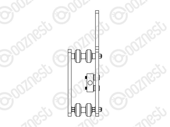
Run any piece of C-Beam extrusion in-between the two rows of wheels. Initially, there may be a small amount of play between the C-Beam and wheels. Turn the assembly upside down so the C-Beam WorkBee CNC Assembly 18 is sitting on the row of wheels with the Aluminium-Spacer-6mms.
-
Starting with one pair of wheels, adjust both Eccentric-Spacer-6mms down onto the C-Beam Extrusion until there is a small amount of friction between both wheels and the C-Beam Extrusion.
-
When adjusting the pair of Eccentric-Spacer-6mms ideally they should be adjusted identically. However, sometimes one will need to be adjusted slightly more than the other to get both wheels engaged with the C-Beam extrusion.
-
Repeat this for the other pair of wheels.
-
Slide the C-Beam extrusion back and forth through the wheels. This should require a small amount of force, and all wheels should spin as it rolls. Also check there is no wobbling of the extrusion. Once happy, double check the tightness of the M5-Nyloc Nuts.
-
-
-
Mate the Z-Plate-Assembly to the X-Carriage-Assembly in the orientation seen above. Use 8 x M5-Low-Profile-20mm bolts and 8 x M5-Nyloc-Nuts to secure the two assemblies together.
-
Make sure the Z-Plate-Assembly is square to the X-Carriage-Assembly.
-
The allen key can be inserted through access holes on the X-Plate-Back to gain access to the bolt heads.
-
-
-
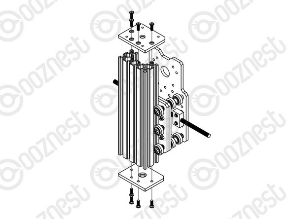
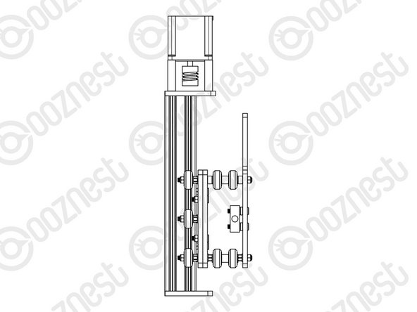
Slide the C-Beam-250mm through the Z-Wheels on the X-Carriage-Assembly.
-
Attach both of the Z-End-Mounts using 8 x M5-Low-Profile-15mm bolts.
-
Tighten the top Z-End-Mount bolts fully.
-
For the bottom Z-End-Mount, tighten the bolts fully, and then loosen by a single full turn (the reason for this will become clear later).
-
-
-
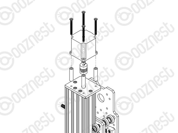
Slide the 1/4” side (the side with the smallest hole) of the Flexible-Coupler onto the shaft of the NEMA23-Stepper-Motor. Don’t tighten it down at this point.
-
Attach the NEMA23-Stepper-Motor to the threaded holes on the Z-End-Mount using 4 x M5-Low-Profile-50mm bolts and 4 x Aluminium-Spacer-40mm’s.
-
Orient the NEMA23-Stepper-Motor so that the wire is towards the back of the X-Carriage-Assembly.
-
-
-
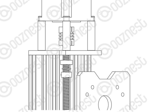
Slide the Z-ACME-Screw through the bottom Z-End-Mount. Then slide on a F688ZZ-Bearing (facing downwards), 8mm-Shim, and a 8mm-Lock-Collar in this order.
-
Thread the Z-ACME-Screw through the ACME-AB-Nut-Block, it may be hard to thread the Z-ACME-Screw through the ACME-AB-Nut-Block for the first time. Once through, slide on a 8mm-Lock-Collar, 8mm-Shim, and a F688ZZ-Bearing (facing upwards) in this order.
-
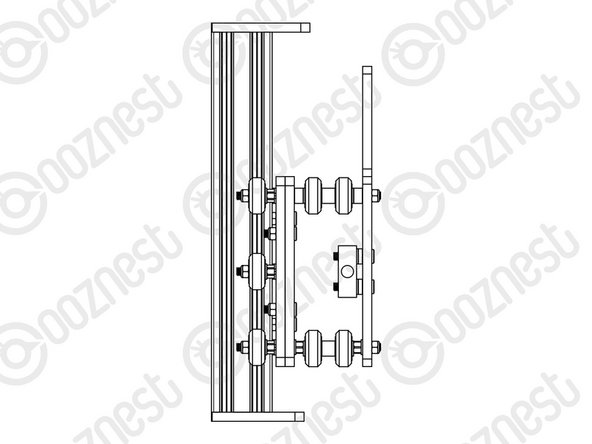
Fully thread through the Z-ACME-Screw until it is touching the NEMA 23-Stepper Motor shaft. Position the Flexible-Coupler so it is half on the Z-ACME-Screw and half on the NEMA23-Stepper-Motor shaft. Once in position, tighten the screws on the Flexible-Coupler.
-
Make sure one is on the flat portion of the motor shaft
-
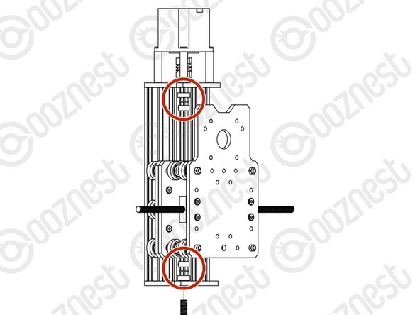
Slide the second F688ZZ-Bearing up the Z-ACME-Screw until it seats in the hole on the top Z-End-Mount, then slide up the 8mm-shim onto the bearing, and finally slide up 8mm-Lock-Collar so it is firmly against the 8mm-Shim and lock it in place using the grub screw on the side.
-
Repeat for the bottom Z-End-Mount.
-
Locate the four M5-Low-Profile-15mm bolts that were left a full turn from tight in Step 9. These can now be fully tightened. Doing this will remove any play that may be present.
-
-
-
Firmly hold the X-Carriage-Assembly, and check for any up and down play in the C-Beam-250mm. If there is any, this is due to backlash in the ACME-AB-Nut-Block. The set screw which was inserted in Step 3 into the ACME-AB-Nut-Block can be screwed downwards to remove this.
-
Do not over tighten this, as it can make the Z ACME-Screw difficult to turn. You can test this by rotating the Flexible-Coupler by hand.
-
It should require a small to medium amount of force. This will need to be rechecked once the router is attached, and periodically checked when in use.
-


Thanks for following the guide. Any issues, please contact us!
Thanks for following the guide. Any issues, please contact us!
Cancel: I did not complete this guide.
61 other people completed this guide.

4 Comments
The M5-Low-Profile-30mm doesn’t come in the hardware box, I have a M5 - Button - Head - Bolt 30mm can I use these ones for Step 1 Z wheels, first bullet point?
Hi Melissa,
I have looked at your order, and you have the Z1+ WorkBee. These manuals are for an older version of the WorkBee.
These are the manuals you should be following: Original WorkBee Z1+ Assembly Manual - V1.0
Robert
Robert -
I have an issue with the F688ZZ-bearing. It got completely stuck mid way through the Z screw. There is no way to unblock it. It feels as if the z-screw got a bit wider mid way. Any suggestions?
Carl Harroch - Resolved on Release Reply
The trickiest bit so far! great fun though! Not there is an 8mm Lock collar and an 8mm clamping collar in the kit - you need the lock collar as per the instructions
Lee Wright - Resolved on Release Reply