
-
-
Attach the V-Slot-2040-750mm to the back two holes on the Y-Plate-Right-Assembly using 2 x M5-Low-Profile-15mm bolts.
-
Attach the C-Beam-750mm to the four non-threaded holes on the Y-Plate-Right Assembly shown above using 4 x M5-Low-Profile-15mm bolts.
-
Loosen the M5-Low-Profile-15mm bolts on the Y-Plate-Left-Assembly by a single full turn (the reason for this will become clear later).
-
-
-
Before the Y-Plate-Left-Assembly can be attached, Tee-Nuts need to be inserted.
-
The Tee-Nuts should be inserted so that the flat face is facing outwards.
-
Insert 2 x Tee-Nuts in to the front facing top slot, 2 x Tee-Nuts in to the front facing bottom slot.
-
Onto each end of the X-ACME-Screw slide on a 8mm-Lock-Collar, 8mm-Shim, and a 688ZZ-Bearing in this order. Make sure the flat side of the 8mm-Shim is against the 688ZZ-Bearing.
-
Slide the X-Carriage-Assembly onto the C-Beam-750mm in the orientation seen above.
-
Repeat Step 1 for the Y-Plate-Left-Assembly, but do not loosen the M5-Low- Profile-15mm bolts this time.
-
Recheck the bottom Eccentric-Spacer-6mms on the X-Carriage-Assembly to make sure they are touching the rail, there is no wobble, and that the X-Carriage-Assembly runs smoothly along the whole length of the C-Beam-750mm.
-
-
-
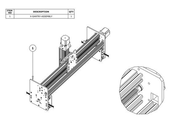
Adjust the X-ACME-Screw so it is touching the NEMA 23-Stepper-Motor shaft. Position the Flexible-Coupler so it is half on the X-ACME-Screw and half on the NEMA23-Stepper-Motor shaft. Once in position, tighten the grub screws on the Flexible-Coupler.
-
Make sure one is on the flat portion of the motor shaft.
-
Slide the 688ZZ-Bearings along the X-ACME-Screw until they seat in the inset on the Y-Plate-Left or Right depending on which side they are on. Then slide the 8mm-shim onto the bearings, and finally slide the 8mm-Lock-Collars so they are firmly against the 8mm-Shim and lock them in place using the grub screw on the side.
-
In Step 1, the six M5-Low-Profile-15mm bolts were left a full turn from tight, these can now be fully tightened. Doing this will remove any play that may be present from in this section.
-
While doing this also place the X-Gantry-Assembly on a flat table, and check that it is flat and square. If it isn’t undo some of the M5- Low-Profile-15mm bolts and adjust it.
-
-
-
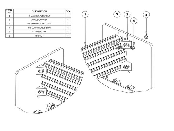
Attach an Angle-Corner to the Y-Plate-Right-Assembly & the front facing top slot of the C-Beam-750mm. A M5-Low-Profile-8mm screws into the Tee-Nut previously inserted, and a M5-Low-Profile-15mm goes though the Angle-Corner and attaches to a M5-Nyloc-Nut on the outside of the Y-Plate-Right-Assembly.
-
Repeat this for the other 3 Angle-Corners in the positions shown above.
-


Thanks for following the guide. Any issues, please contact us!
Thanks for following the guide. Any issues, please contact us!
Cancel: I did not complete this guide.
4 other people completed this guide.