
-
-
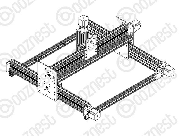
Slide a C-Beam-750mm through each set of wheels on the X-Gantry-Assembly. The Y-ACME-Screws go inside the ‘C’ Channel.
-
Rest the ends of the C-Beam-750mm on 2 x V-Slot-2040-745mm’s. The ends of the extrusions should be flush with the sides of each other.
-
-
-
If possible while carrying out the below steps get a second person to hold the machine square.
-
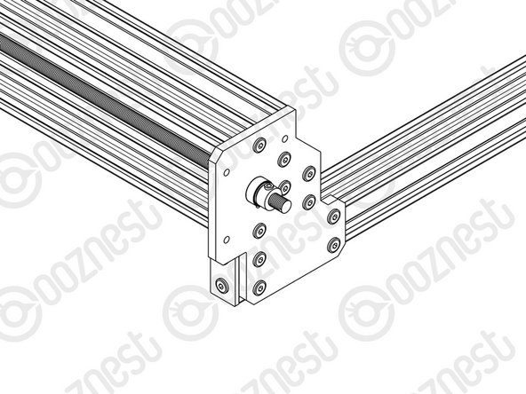
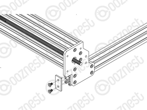
Slide the X-Gantry-Assembly to the front, and attach a Y-End-Plate to the front left corner, first using 4 x M5-Low-Profile-15mms, which screw into the tapped holes on the C-Beam-750mm.
-
Insert 2 x Tee-Nuts into the front facing top and bottom slots of the V-Slot-2040- 745mm. Adjust the Tee-Nuts so they line up with the holes on the Y-End-Plate.
-
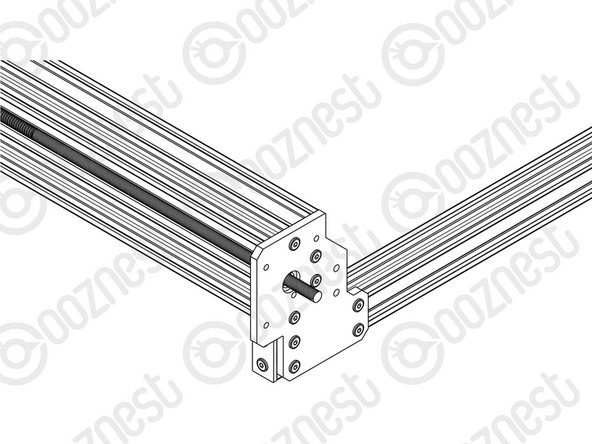
Secure the Y-End-Plate to the V-Slot-2040-745mm using 4 x M5-Low-Profile- 12mms. Ensure the end of the V-Slot-2040-745mm is flush with the side of the C Beam-750mm.
-
Square the base, and repeat for the Y-End-Plate on the opposite end of the front V-Slot-2040-745mm.
-
Slide the X-Gantry-Assembly to the back. Square the base, and repeat all the above for the back V-Slot-2040-745mm.
-
-
-
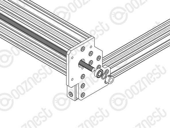
Adjust the left Y-ACME-Screw (as if looking from the front) so roughly 10mm is protruding from the Y-End-Plate at the back of the machine. Slide onto the end a F688zz-Bearing, 8mm-Shim and 8mm-Clamping-Collar, and inset the F688zz-Bearing into the hole on the Y-End-Plate.
-
Slide the 1/4” side (the side with the smallest hole) of the Flexible-Coupler onto the shaft of the NEMA23-Stepper-Motor. Don’t tighten it down at this point.
-
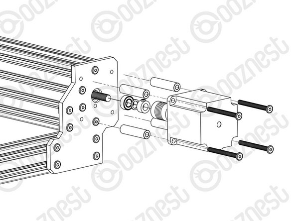
Attach the NEMA23-Stepper-Motor to the threaded holes on the Y-End-Plate using 4 x M5-Low-Profile-50mm bolts and 4 x Aluminium-Spacer-40mms. Adjust the Y-ACME-Screw so it is touching the NEMA 23-Stepper-Motor shaft.
-
Orient the NEMA23-Stepper-Motor so the wire is facing downwards.
-
While pushing the 8mm-Clamping-Collar against the 8mm-Shim and F688zz-Bearing into the recess on the Y-End-Plate, tighten the clamping bolt on the 8mm-Clamping-Collar.
-
Tighten the grub screws on the Flexible-Coupler. Make sure one is on the flat portion of the motor shaft.
-
Repeat for the final NEMA23-Stepper-Motor attaching it to the Y-End Plate-Left on the back right of the machine.
-
-
-
At the front of the machine, onto the two Y-ACME-Screws protruding from the Y-End-Plates slide on a F688zz-Bearing, 8mm-shim, and a 8mm-Clamping-Collar.
-
While pushing the 8mm-Clamping-Collar against the 8mm-Shim and F688zz-Bearing into the hole on the Y-Plate-End-Plates, tighten the clamping bolt on the 8mm-Clamping-Collar.
-
-
-
Attach an End-Cap to front left end of the V-Slot-2040-745mm using 2 x M5-Low-Profile-8mm bolts.
-
Repeat this for the other 3 x End-Caps on the other bare ends of the V-Slot-2040-745mms.
-


Thanks for following the guide. Any issues, please contact us!
Thanks for following the guide. Any issues, please contact us!
Cancel: I did not complete this guide.
47 other people completed this guide.

One Comment
Step 5- End Caps, they need to be removed in order to do the steps in the next module. This step should be skipped for now.
Adam J Barnett - Resolved on Release Reply