
-
-
Prepare 16 x Universal-L-Brackets with a M5-Button-Head-Bolt-8mm through each hole and a M5-Tee-Nut slightly threaded onto it.
-
The flat side of the M5-Tee-Nut should be facing the Universal-L-Bracket.
-
-
-
With a Universal-L-Bracket in hand take note that the holes down one side are closer to the corner of the Universal-L-Bracket than the other side.
-
Slide the side of the Universal-L-Bracket with the holes closest to the corner onto one end of an Extrusion-C.
-
Align the Universal-L-Bracket flush with the end of Extrusion-C and tighten the M5-Button-Head-Bolts-8mm.
-
Repeat for the other 3 corners of the Extrusion-C.
-
Repeat all points above for the other 3 Extrusion-C's.
-
-
-
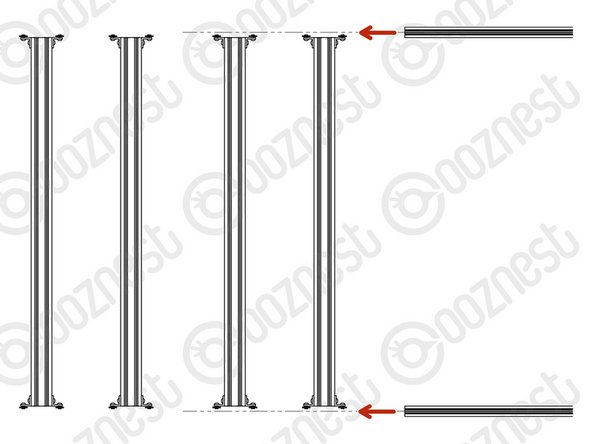
Lay all Extrusion-C's out on a flat table with the ends roughly flush with each other as in Image 1.
-
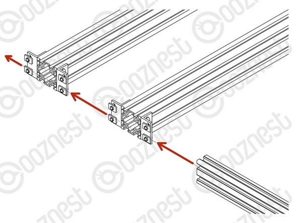
Front and Back, slide a Extrusion-A through all the Tee-Nuts on each Extrusion-C.
-
Roughly evenly space the Extrusion-C's along the Extrusion-A's.
-
Keep them loose, they will be adjusted in the next Step.
-
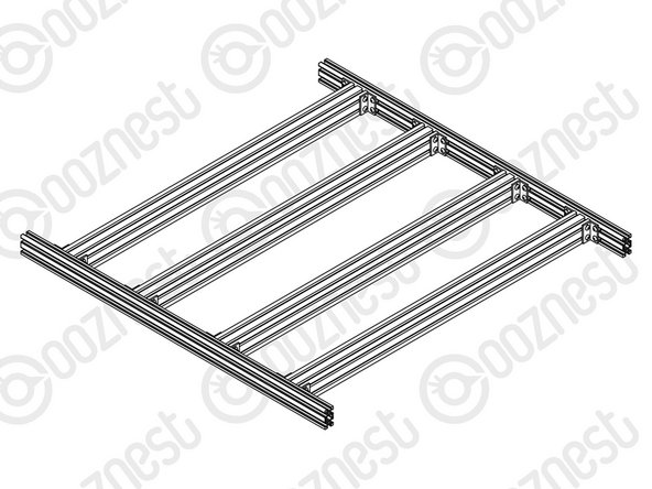
You should end up with something that looks similar to Image 3.
-
-
-
It is important that you carry out the below on a perfectly flat surface.
-
While doing the below, you will need an engineers square.
-
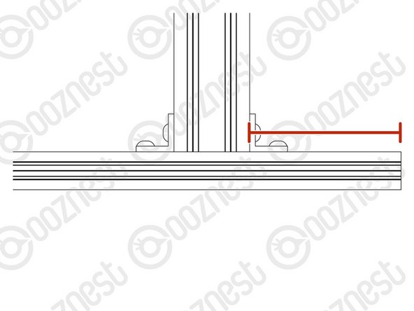
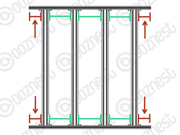
The two outside Extrusion-C's should be spaced 80mm in from the end of the Extrusion-A's.
-
Once in position, check they are square with the Extrusion-A's, then tighten all the M5-Button-Head-Bolt-8mm on these two Extrusion-C's.
-
The central two Extrusion-C's should be spaced evenly so the 3 gaps are of equal size.
-
Once in position, check they are square with the Extrusion-A's, then tighten all the M5-Button-Head-Bolt-8mm on these two Extrusion-C's.
-
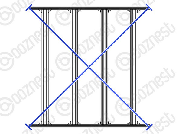
To double-check the base is square, measure the diagonals. They should be the same.
-
Adjust if needed.
-
-
-
You are getting to see the scale of it now. Keep the Base-Assembly on the table ready for the next guide.
-
Guide Complete - Proceed to 6. Y-Gantry Assembly
-


Thanks for following the guide. Any issues, please contact us!
Thanks for following the guide. Any issues, please contact us!
Cancel: I did not complete this guide.
76 other people completed this guide.
