
-
-
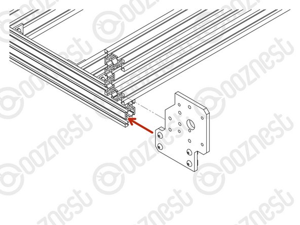
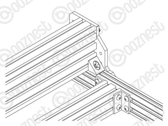
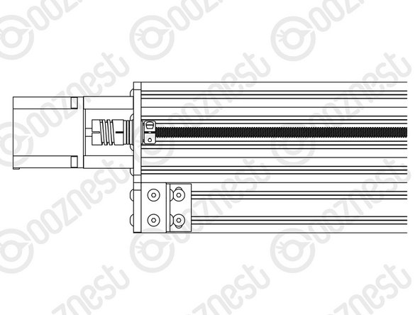
Prepare 2 x Y-End-Plate in the orientation shown in Image 1, with a M5-Button-Head-Bolt-12mm through each of the 4 bottom holes and a M5-Tee-Nut slightly threaded onto each one.
-
The flat side of the M5-Tee-Nut should be facing the Y-End-Plate.
-
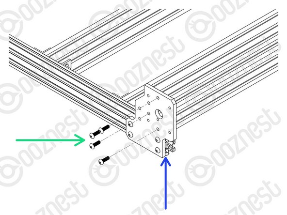
Repeat the above 2 points, but for 2 x Y-End-Plate in the orientation shown Image 2.
-
-
-
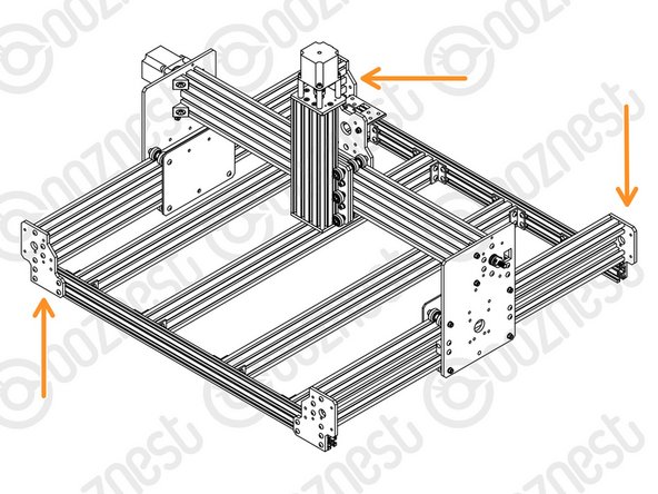
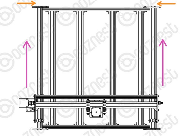
Position the two Extrusion-F's on top of the Base-Assembly.
-
Carefully slide the Y-Carriages on the X-Gantry through the Extrusion-F's
-
Adjust the position of each Extrusion-F so the ends are flush with the corners of the Base-Assembly.
-
-
-
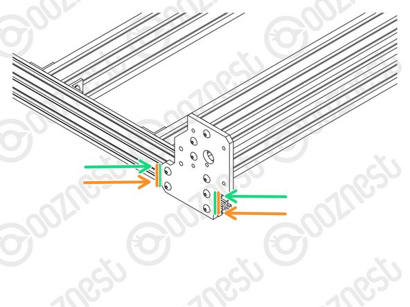
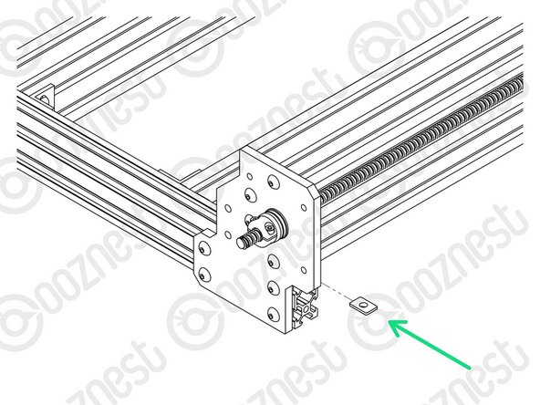
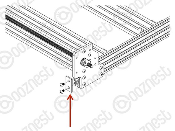
At the front right corner of the machine, slide a Y-End-Plate into the two front-facing slots of Extrusion-A.
-
Attach the Y-End-Plate to Extrusion-F using 4 x M5-Button-Head-Bolt-16mm through the non-threaded holes on the Y-End-Plate and into the threaded holes on Extrusion-F.
-
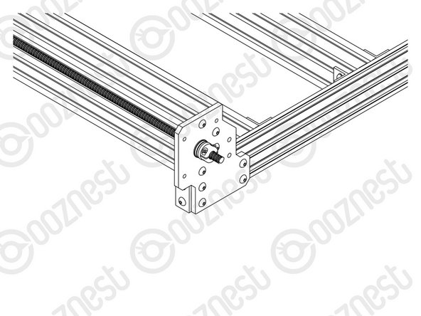
Make sure the side of the Y-End-Plate is flush with the end of Extrusion-A.
-
Then tighten all the M5-Button-Head-Bolt-12mm on the Y-End-Plate.
-
Repeat for the other 3 corners of the machine.
-
-
-
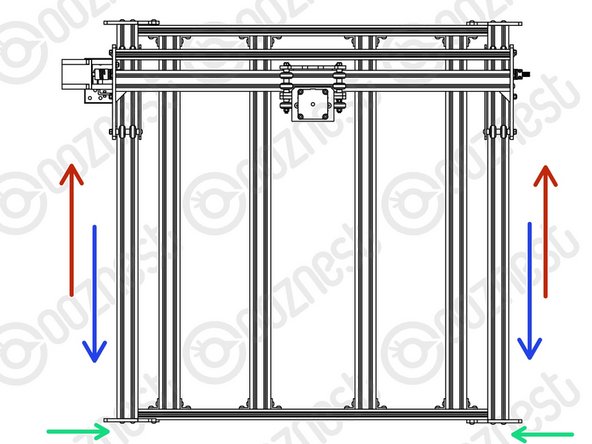
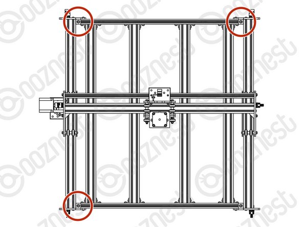
Slide the X-Gantry to the back of the machine as far as it will go.
-
Slightly loosen the 4 x M5-Button-Head-Bolt-12mm on each of the two front Y-End-Plates.
-
Carefully slide the X-Gantry to the front of the machine as far as it will go.
-
Re-tighten the M5-Button-Head-Bolt-12mm loosened in the green point above.
-
Keep the machine at the front and slightly loosen the 4 x M5-Button-Head-Bolt-12mm on each of the two back Y-End-Plates.
-
Carefully slide the X-Gantry to the back of the machine as far as it will go.
-
Re-tighten the M5-Button-Head-Bolt-12mm loosened in the orange point above.
-
Slide the X-Gantry back and forth. It should run smoothly without binding.
-
-
-
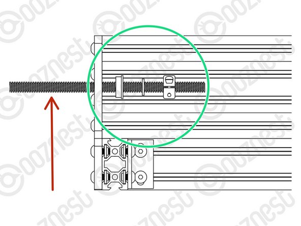
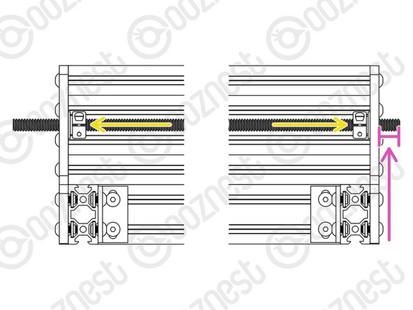
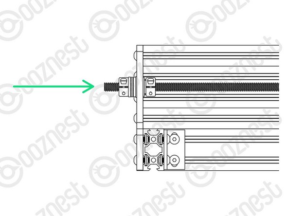
Insert a Lead-Screw-Y through the large 16mm hole on the front right Y-End-Plate so it protrudes into the channel on Extrusion-F roughly 100mm.
-
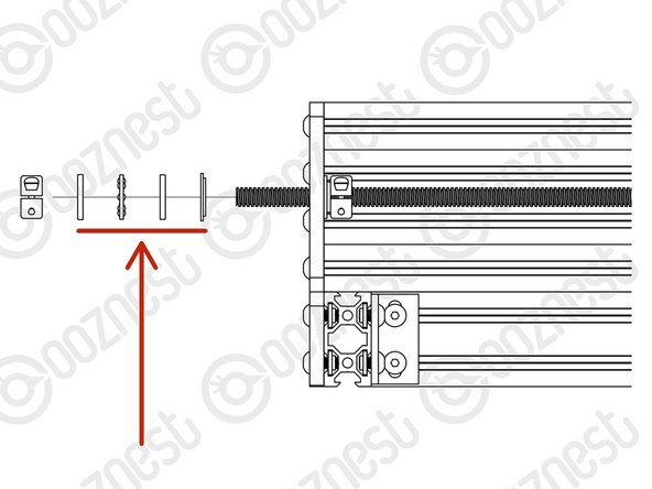
Slide onto Lead-Screw-Y a Flanged-Radial-Bearing - ->- - Rubber-Bushing - ->- - Clamping-Collar.
-
Insert the Lead-Screw-Y further into the channel, and then thread it through both Nut-Blocks on the Y-Carriage-Right.
-
The Nut-Blocks should be loose so their position can be adjusted to allow Lead-Screw-X to thread through.
-
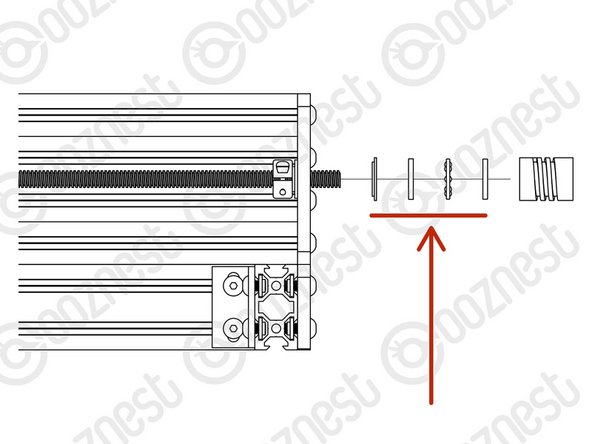
Once through the Nut-Blocks, slide onto Lead-Screw-Y a Clamping-Collar - ->- - Rubber-Bushing - ->- - Flanged-Radial-Bearing.
-
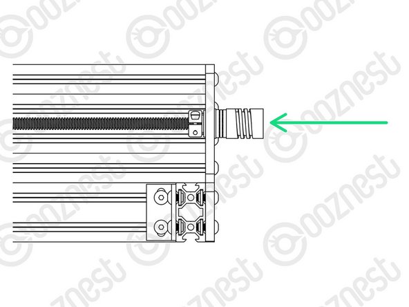
Thread through Lead-Screw-Y further so it goes through the large 16mm hole on the back right Y-End-Plate. Adjust the Lead-Screw so there is 14mm protruding from the back right Y-End-Plate.
-
Seat the Flanged-Radial-Bearings into the Y-End-Plates, slide the Rubber-Bushing against the Flanged-Radial-Bearings and finally slide the Clamping-Collars so they are against against the Rubber-Bushings. Slightly tighten the Clamping-Collars.
-
Repeat all the above points for the left Y-End-Plates and Y-Carriage-Left
-
-
-
Thrust-Bearings come in 3 parts. Thrust-Bearing-Housing-Washer, Thrust-Bearing-Caged-Roller and Thrust-Bearing-Shaft-Washer
-
The Thrust-Bearing-Housing-Washer and Thrust-Bearing-Shaft-Washer look exactly the same. They are not.
-
We recommend adding a generous amount of bearing Lubricant to the grooved face of both washers.
-
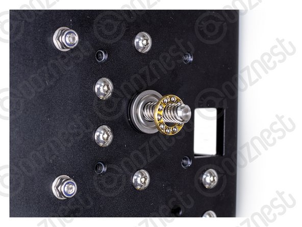
On the Lead-Screw-Y protruding from the front right Y-End-Plate, slide on a Nylon-Shoulder-Washer - ->- - Thrust-Bearing-Housing-Washer - ->- - Thrust-Bearing-Caged-Roller - ->- - Thrust-Bearing-Shaft-Washer
-
The Nylon-Shoulder-Washer seats in the 16mm hole on the Y-End-Plate.
-
The Thrust-Bearing-Caged-Roller seats in the grooves on the Thrust-Bearing washers. Same orientation as before.
-
Finally slide on a Clamping Collar. While pushing the Clamping-Collar against the Thrust-Bearing assembly, tighten the Clamping-Collar.
-
Repeat all the above for the front left Y-End-Plate.
-
-
-
On the Lead-Screw-Y protruding from the back right Y-End-Plate slide on a Nylon-Shoulder-Washer - ->- - Thrust-Bearing-Housing-Washer - ->- - Thrust-Bearing-Caged-Roller - ->- - Thrust-Bearing-Shaft-Washer
-
The Nylon-Shoulder-Washer seats in the 16mm hole on the Y-End-Plate.
-
The Thrust-Bearing-Caged-Roller seats in the grooves on the Thrust-Bearing washers. Same orientation as before.
-
Finally slide on a Flexible-Coupler. While pushing the Flexible-Coupler against the Thrust-Bearing assembly, tighten Flexible-Coupler
-
On the Flexible-Coupler tighten the clamping bolt first and then the grub screw.
-
Repeat all the above for the back left Y-End-Plate.
-
-
-
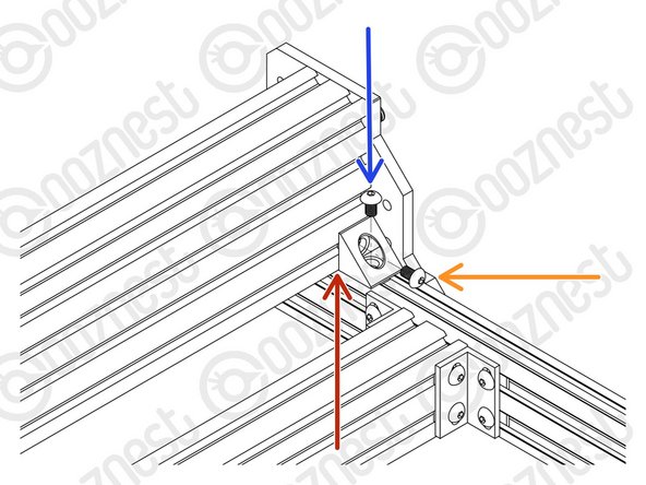
At the front right corner of the machine, an Angle-Corner goes in the corner between Extrusion-A and Extrusion-F.
-
First slide an M5-Tee-Nut into the top slot of Extrusion-A.
-
The flat face of the M5-Tee-Nut should be facing upwards.
-
Use a M5-Button-Head-Bolt-8mm and the previously inserted M5-Tee-Nut to attach it to Extrusion-A.
-
To attach it to Extrusion-F, use a M5-Button-Head-Bolt-8mm and M5-Drop-In-Tee-Nut.
-
M5-Drop-In-Tee-Nuts do not need to slide in from the end.
-
They go in to the slot parallel, when the bolt engages they should spin perpendicular to the slot and bite into the underside of the slot.
-
-
-
Repeat the previous step for the other 3 corners.
-
Double-check the M5-Drop-In-Tee-Nuts are correctly engaged with Extrusion-F.
-
-
-
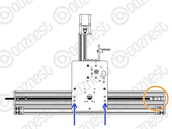
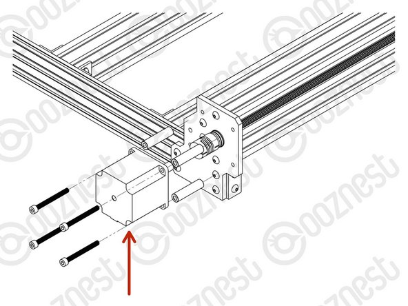
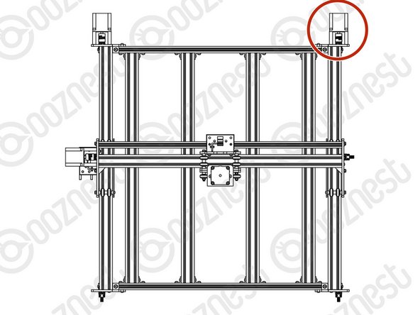
Attach a Stepper-Motor to the threaded holes on the back left Y-End-Plate using 4 x M5-Cap-Head-Bolt-50mm and 4 x Aluminium-Spacer-40mms.
-
Orient the Stepper-Motor so that the wire is facing down.
-
The shaft of the Stepper-Motor goes into the Flexible-Coupler.
-
On the Stepper-Motor side make sure the Flexible-Coupler grub screw is on the flat portion of the Stepper-Motor shaft.
-
Once in position, tighten the clamping bolt first, then the grub screw.
-
The Lead-Screw side was tightened earlier in this guide.
-
-
-
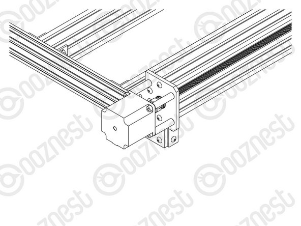
Repeat the previous step for the right Y-Axis Stepper-Motor.
-
-
-
Attach an End-Cap to the front left end of Extrusion-A using 2 x M5-Button-Head-Bolt-8mm.
-
Repeat this for the other 3 bare ends of the Extrusion-A's.
-
-
-
Wow, what a difference. The machine can stay where it is now, we are going to be adding more stuff on!
-
Guide Complete - Proceed to 7. Router Mount
-


Thanks for following the guide. Any issues, please contact us!
Thanks for following the guide. Any issues, please contact us!
Cancel: I did not complete this guide.
74 other people completed this guide.

9 Comments
Very impressed with the quality of the components, excellent instructions, I like the components being in very well labelled bags. I am slowly and meticulously working through getting each part out as I get to them and returning bags to correct boxes when I have finished a section. I suspect I am benefiting from others comments being implemented. Really enjoying the process and so far it all seems to move smoothly and is square to the mm. Here’s to the next stage. Thank you.
(second part of my comment, but why require/demand to be signed in, welcome ALL comments)
……….would have been much better and would have saved time. Then…. it would be good to describe the sections a bit more in the overview. Then the extrusion numbering: you have to remove the labels printed on them as all are in the way except the short extrusion D for the Z-axis. Many times I am was wondering where extrusion A, B, E or F actually were. Another issues: the glue of the labels is super hard to remove, even with alcohol or aceton; you really have to use a label glue dissolvent to remove it.
But my machine Z+ 1500x1500 is no fully assumbled apart from the table below it and it all seems to work fine sofar. It’s for me the first time I do this, although my experience with 3D printers and Fusion360 comes in handy as it is not really so far apart.
Greetings,
Mark Wiersma
Mark Wiersma - Resolved on Release Reply
Hi Mark,
Thanks for your comment. The maximum comment length is set by Dozuki (The software behind learn.ooznest.co.uk) and we have no control over it I am afraid.
The same applies to having to be logged in to comment (On Prusa manuals you need to be logged into to comment also)
I believe Prusa uses the same software for their guides.
I have looked at Prusa guides and can see they have steps about collecting the parts, which is a good idea, and something we can think about adding.
Did you see our Box Cheat Sheet here to help locate the parts: https://ooznest.co.uk/wp-content/uploads...
For the extrusion, the labels should have been peelable, I have raised this as an issue, as to why they are not peelable, as I know we have specific labels for the extrusions that should come off easily. My apologies they were difficult to get off in your case.
Thanks for all your other points, they have been noted.
Robert
Robert -