
-
-
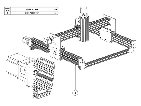
Slide a C-Beam-750mm through each set of wheels on the X-Gantry-Assembly. The Y ACME-Screws go inside the ‘C’ Channel.
-
Rest the ends of the C-Beam-750mm on 2 x V-Slot-2040-745mm’s. The ends of the extrusions should be flush with the sides of each other.
-
-
-
Onto each end of the Y-ACME-Screws slide on a 8mm-Lock-Collar, 8mm-Shim, and a 688ZZ-Bearing in this order. Make sure the flat side of the 8mm-Shim is against the 688ZZ-Bearing.
-
Slide the X-Gantry-Assembly to the front, and attach a Y-End-Plate-Left to the front left corner, first using 4 x M5-Low-Profile-15mms, which screw into the tapped holes on the C-Beam-750mm.
-
Insert 2 x Tee-Nuts into the front facing top and bottom slots of the V-Slot-2040- 745mm. Adjust the Tee-Nuts so they line up with the holes on the Y-End-Plate-Left.
-
Secure the Y-End-Plate-Left to the V-Slot-2040-745mm using 4 x M5-Low-Profile- 12mms. Ensure the end of the V-Slot-2040-745mm is flush with the side of the C Beam-750mm.
-
Square the base, and repeat for the Y-End-Plate-Right on the opposite end of the front V-Slot-2040-745mm. If possible, get a second person to hold the base square while tightening the bolts.
-
Slide the X-Gantry-Assembly to the back. Square the base, and repeat all the above for the back V-Slot-2040-745mm.
-
Loosen the M5-Low-Profile-15mm/12mm bolts on the front Y-End-Plate-Left & Y-End Plate-Right by a single full turn (the reason for this will become clear later).
-
-
-
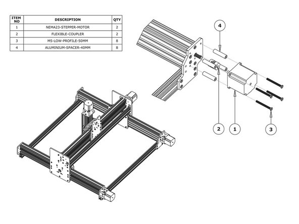
Slide the 1/4” side (the side with the smallest hole) of the Flexible-Coupler onto the shaft of the NEMA23-Stepper-Motor. Don’t tighten it down at this point.
-
Attach the NEMA23-Stepper-Motor to the threaded holes on the back left Y-End-Plate Right (as if looking from the front) using 4 x M5-Low-Profile-50mm bolts and 4 x Aluminium-Spacer-40mms.
-
Orient the NEMA23-Stepper-Motor so the wire is facing downwards.
-
Repeat for the final NEMA23-Stepper-Motor attaching it to the Y-End Plate-Left on the back right of the machine (as if looking from the front).
-
-
-
Adjust the Y-ACME-Screws so they are touching the NEMA23-Stepper-Motor shafts. Position the Flexible-Couplers so they are half on the Y-ACME-Screws and half on the NEMA23-Stepper-Motor shafts. Once in position, tighten the grub screws on the Flexible-Couplers.
-
Make sure one is on the flat portion of the motor shaft.
-
For the left hand Y-ACME-Screw, slide the 688ZZ-Bearings along the Y-ACME-Screw until they seat in the insets on the Y-End-Plate-Left or Right depending on which side they are on.
-
Then slide the 8mm-shim onto the bearings, and finally slide the 8mm Lock-Collars so they are firmly against the 8mm-Shims and lock them in place using the grub screw on the side.
-
Repeat for the right hand Y-ACME-Screw.
-
In Step 2, the M5-Low-Profile-15mm/12mm bolts were left a full turn from tight, these can now be fully tightened.
-
Doing this will remove any play that may be present from. If possible, get a second person to hold the base square while tightening the bolts.
-
-
-
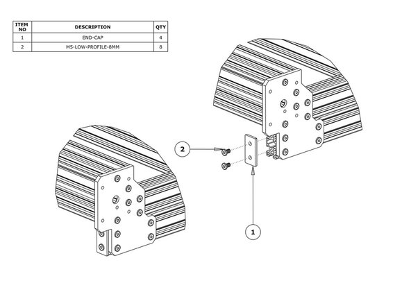
Attach an End-Cap to front left end of the V-Slot-2040-745mm using 2 x M5-Low-Profile-8mm bolts.
-
Repeat this for the other 3 x End-Caps on the other bare ends of the V-Slot-2040-745mms.
-


Thanks for following the guide. Any issues, please contact us!
Thanks for following the guide. Any issues, please contact us!
Cancel: I did not complete this guide.
2 other people completed this guide.