
-
-
The Z-Limit-Switch sits in-between two sets of wheels. Directly opposite there is a hole. Feed the wires through this hole (red circle). If there is a connector on the end of the wire, this will need to be removed to get it through the hole. To do this, on the back side of the connector there is a row of 3 slits.
-
Push a small screwdriver into this slit, while pulling on the corresponding wire. The wire should release. Repeat for the second wire. Re-attach the connector after feeding the wires through the hole. The wires should go back inside the connector the same order as the other limit switches in the kit.
-
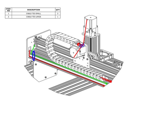
As shown by the green line above bring the Z-Limit-Switch wires up the X-Plate-Back, and feed it through the X-Drag-Chain.
-
Secure the wires using Cable-Tie-Smalls to the points marked with blue circles. To stop it snagging on anything the wire should be pulled tight.
-
-
-
For the Z-Axis Motor Wire that is inside the X-Drag-Chain, connect it to the pigtail on Z-Axis stepper motor. Making sure there is enough slack for the full travel of the Z-Axis shown in red, secure the wire to the X-Drag-Moving-End-Mount using a Cable-Tie-Small, shown by the small blue circle above.
-
The lead on the X-Axis limit switch should be secured to the V-Slot-2040-750mm using a Cable-Tie-Large at the position shown by the blue oval above. Then run the lead along to the other end of V-Slot-2040-750mm - it can be tucked into one of the slots.
-
-
-
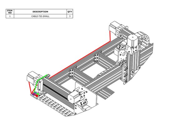
For the Z-Axis motor wire that is inside the X-Drag-Chain, connect it to the pigtail on Z-Axis stepper motor. Making sure there is enough slack for the full travel of the Z-Axis, secure the wire to the X-Drag-Moving-End-Mount using a Cable-Tie-Small, shown by the small blue circle above.
-
In a similar fashion as previous for the X-Axis motor wire connect it to the pigtail on the X-Axis stepper motor wire. Secure it to the X-Drag-Moving-End-Mount
-
Connect the right Y-Axis motor wire to the pigtail on the right hand Y-Axis stepper motor (as if looking from the front). Feed it through the square hole on the Y-Plate.
-
The lead on the X-Axis limit switch and stepper motor wire should be secured to the V-Slot-2040-750mm using a Cable-Tie-Large at the position shown by the blue oval. Then run the wires along to the other end of V-Slot-2040-750mm - they can be tucked into the slots.
-
-
-
Connect the two stepper motor wires in the Y-Drag-Chain to their corresponding pigtails on the Y-Axis stepper motors. The longer wire should connect to the right hand stepper motor.
-
Secure the stepper motor wires to the Y-Axis-Fixed-End-Mount using Cable-Tie Smalls. The wire for the right hand stepper motor can be tucked into a slot on one of the extrusions along the back.
-
Secure the lead on the Y-Axis limit switch to the Y-Axis-Fixed-End-Mount using a Cable-Tie-Small.
-
-
-
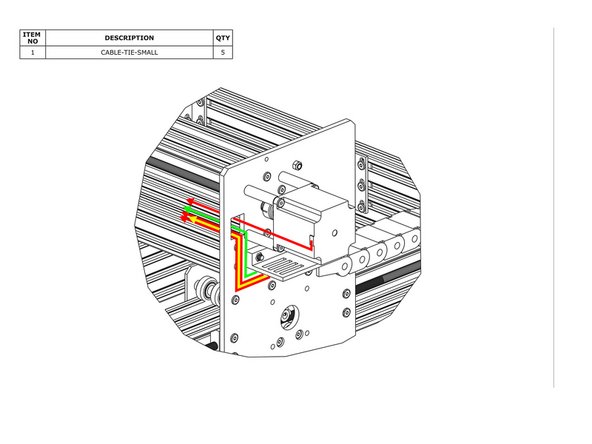
Connect the X-Axis motor wire to the pigtail on the X-Axis stepper motor and feed it through the square hole on the Y-Plate.
-
Inside the Y-Drag-Chain there should be two stepper motor wires (red line), a power supply wire (yellow line), and a limit switch wire (green line). Feed all of these through the square hole on the Y-Plate.
-
Remove any slack inside the Y-Drag Chain, and then secure these 4 wires to the Y-Drag-Chain-Moving-End-Mount using Cable-Tie-Smalls.
-
-
-
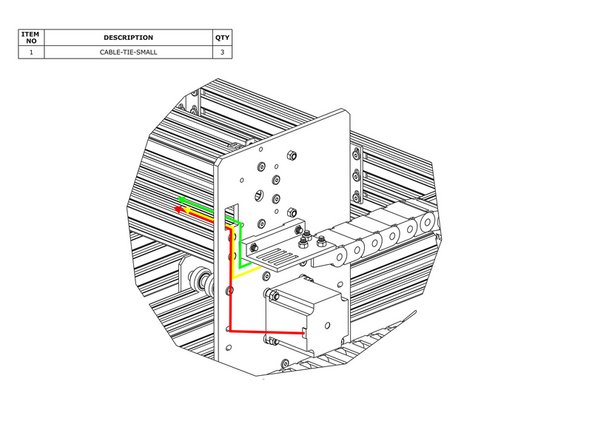
Connect the left Y-Axis motor wire to the pigtail on the left hand Y-Axis stepper motor (if looking from the front) and feed it through the square hole on the Y-Plate.
-
Inside the Y-Drag-Chain there should be a power supply wire (yellow line), and a limit switch wire (green line).
-
Feed all of these through the square hole on the Y-Plate. Remove any slack inside the Y-Drag-Chain, and then secure these 2 wires to the Y-Drag-Chain-Moving-End-Mount using Cable-Tie-Smalls.
-


Thanks for following the guide. Any issues, please contact us!
Thanks for following the guide. Any issues, please contact us!
Cancel: I did not complete this guide.
2 other people completed this guide.