
-
-
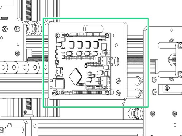
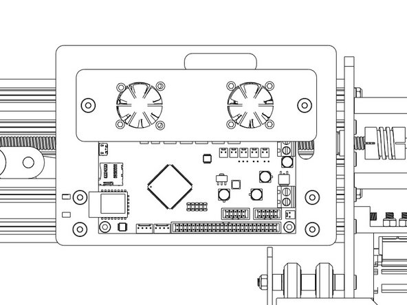
Making sure the board is orientated in the correct way as displayed in the image.
-
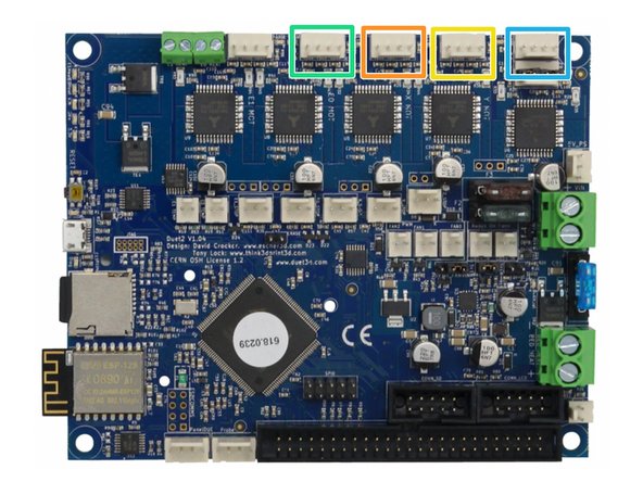
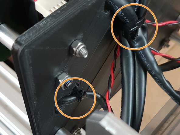
The Large Cable Tie highlighted in Orange is for the 4 Stepper Motor Cables and the Limit Switches.
-
The Small Cable Tie highlighted in Red is for the power cable.
-
The Small Cable Tie highlighted in Yellow is only needed if you have the Ethernet Version, and is to secure the Ethernet Cable.
-
-
-
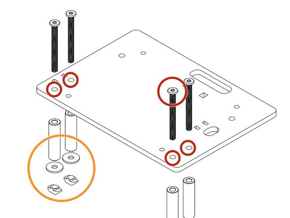
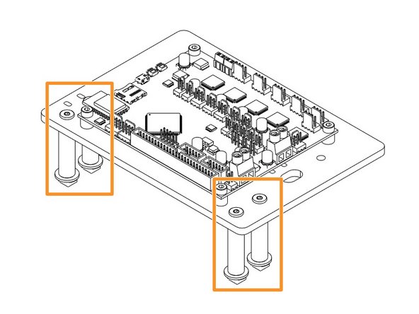
Insert a M4-Cap-Head-Bolt-20mm through each hole on all 4 corners on the Duet 3D Controller.
-
Onto each bolt slide a 1/4"-Nylon-Spacer.
-
Now it is time to join the Duet to the Duet Mount. Insert the bolts into the holes on the Duet Mount and secure using 4 x M4-Nyloc-Nuts.
-
-
-
If you have received the Duet Wifi External Antenna version please follow this Step, if not proceed to Step 4.
-
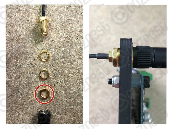
Unscrew the antenna wire from the antenna arm. There will then be 4 parts, antenna wire, star washer, spring washer, hex nut, antenna arm.
-
Discard the hex nut as it is not needed for the assembly.
-
Insert the Antenna wire from the back of the Duet Mount with the spring washer. Once pushed through add the star washer and screw on the antenna arm.
-
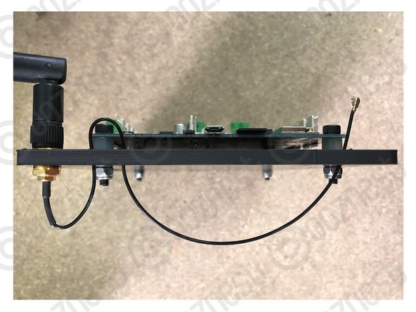
Follow image 2 to route your cable through the holes on the Duet Mount.
-
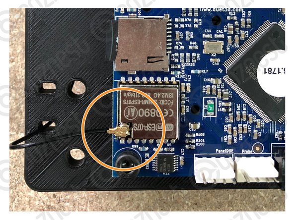
Push the antenna fitting onto the Wifi module until it clicks into place.
-
-
-
--- WorkBee 2.2.1 ---
-
Insert 4 x M5-Low-Profile-50mm bolts through the holes indicated in the image.
-
Place a Aluminium-Spacer-40mm Spacers over each bolt followed by a Slot-Washer and finally a M5-Drop-In-Tee-Nut.
-
Once assembled line up with the 2040 Extrusion on the right hand side of the machine and fix into place tightening the bolts until the M5-Drop-In-Tee-Nuts engage
-
--- WorkBee 2.2 ---
-
Insert 4 x M5-Low-Profile-50mm bolts through the holes indicated in the image.
-
Place a Aluminium-Spacer-1-1/2" Spacers over each bolt followed by a Slot-Washer and finally a M5-Drop-In-Tee-Nut.
-
Once assembled line up with the 2040 Extrusion on the right hand side of the machine and fix into place tightening the bolts until the M5-Drop-In-Tee-Nuts engage
-
-
-
The Mains Power should remain off during all wiring of the Duet Controller.
-
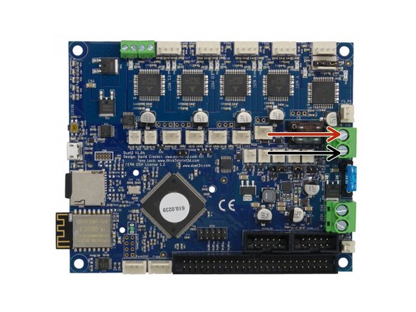
PSU Cable from Power Supply - Connect Red Positive Wire into the Top Screw Terminal and Black into Bottom Screw Terminal.
-
-
-
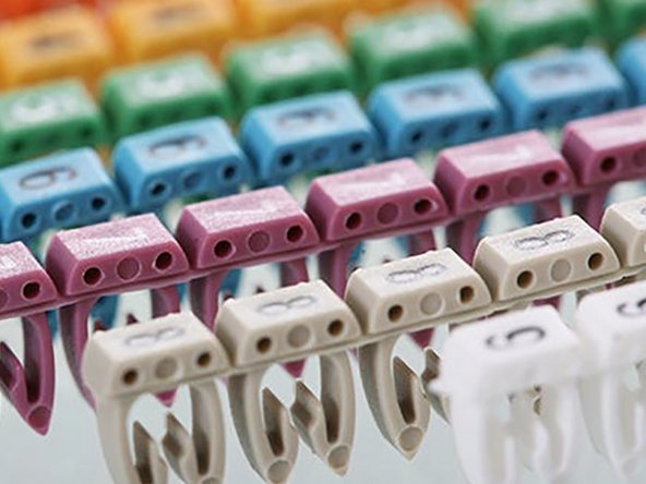
If the wires in your kit have white printed tags, please ignore this step. Each wire, at the connector end has a coloured clip with a number. This colour and number identifies this wire. Please see key below.
-
(0)(Black) X-Axis Limit Switch
-
(1)(Brown) Y-Axis Limit Switch
-
(2)(Red) Z-Axis Limit Switch
-
(3)(Orange) X-Axis Stepper Motor Wire
-
(4)(Yellow) Left Y-Axis Stepper Motor Wire
-
(5)(Green) Right Y-Axis Stepper Motor Wire
-
(6)(Light Blue) Z-Axis Stepper Motor Wire
-
-
-
The connectors for the Duet controller are keyed, so there is only one way which they can plug in.
-
(0)(Black) X-Axis Limit Switch
-
(1)(Brown) Y-Axis Limit Switch
-
(2)(Red) Z-Axis Limit Switch
-
Fans connected to either of the Always on Fan Terminals.
-
-
-
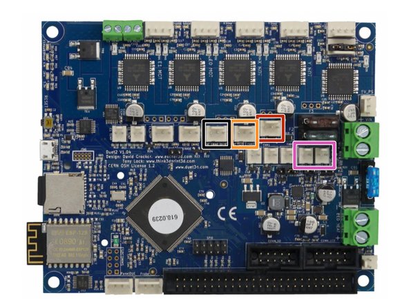
The connectors for the Duet controller are keyed, so there is only one way which they can plug in.
-
(3)(Orange) X-Axis Stepper Motor Wire.
-
(4)(Yellow) Left Y-Axis Stepper Motor Wire.
-
(5)(Green) Right Y-Axis Stepper Motor Wire.
-
(6)(Light Blue) Z-Axis Stepper Motor Wire.
-
-
-
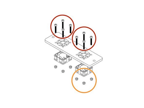
Use 8 x M3-Cap-Head-Bolt-20mms & 8 x M3-Nyloc-Nuts secure the fans highlighted in Yellow onto the Mount with the Fan label facing outward.
-
--- WorkBee 2.2.1 ---
-
Thread 2 x M5-Low-Profile-60mm Bolts through the fan mount. Then slide the a Aluminium-Spacer-40mm highlighted in Green over each bolt.
-
--- WorkBee 2.2 ---
-
Thread 2 x M5-Low-Profile-55mm Bolts through the fan mount. Then slide the a Aluminium-Spacer-1-1/2" highlighted in Green over each bolt.
-
Now attach to the Main Board mount using 2 x M5-Nyloc-Nuts.
-
Connect the fans to 'Always On' Fan connection of your Duet Controller before tightening the M5 Nyloc Nuts.
-
-
-
Using the already inserted cable ties fix the wires into place securely to prevent any unnecessary movement and to keep the machine looking neat!
-
If you have the Ethernet version also secure that.
-


Thanks for following the guide. Any issues, please contact us!
Thanks for following the guide. Any issues, please contact us!
Cancel: I did not complete this guide.
21 other people completed this guide.
