
-
-
Making sure the board is orientated in the correct way as displayed in the image.
-
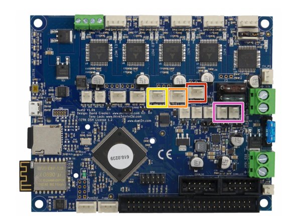
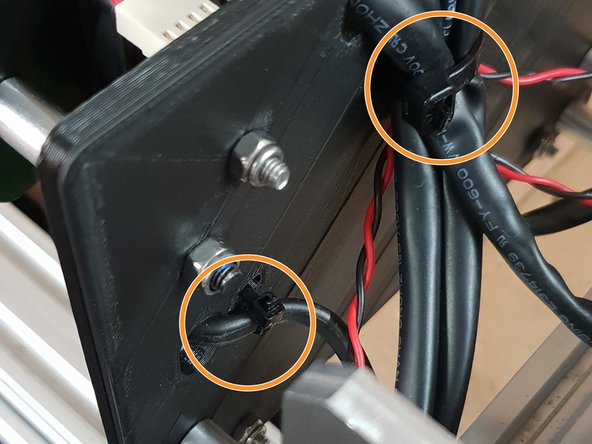
The Large Cable Tie highlighted in Orange is for the 4 Stepper Motor Cables and the Limit Switches.
-
The Small Cable Tie highlighted in Red is for the power cable.
-
The Small Cable Tie highlighted in Yellow is only needed if you have the Ethernet Version, and is to secure the Ethernet Cable.
-
-
-
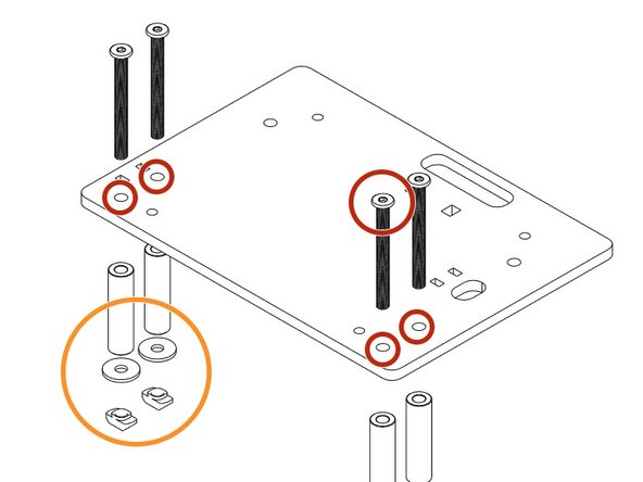
Insert a M4 Cap Head Bolt 20mm through each hole on all 4 corners on the Duet 3D Controller.
-
Onto each bolt slide a 1/4" Nylon Spacer.
-
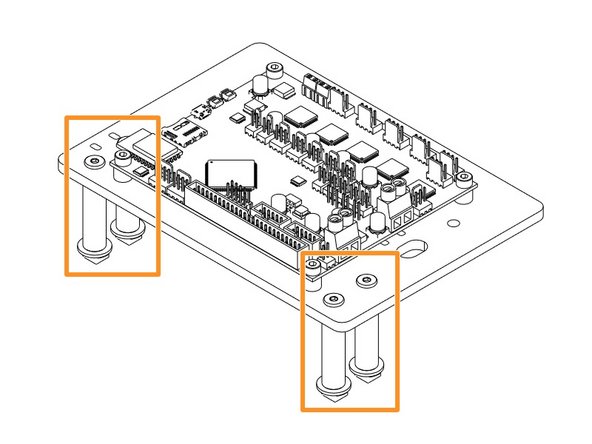
Now it is time to join the Duet to the Duet Mount. Insert the bolts into the holes on the Duet Mount and secure using 4 x M4 Nyloc Nuts.
-
-
-
Insert 4 x M5 Low Profile Bolts through the holes indicated in the image.
-
Place a 1-1/2" Aluminium Spacers over each bolt followed by a Slot Washer and finally a M5 Drop in Tee Nut.
-
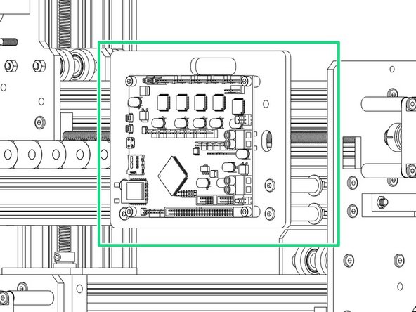
Once assembled line up with the 2040 Extrusion on the right hand side of the machine and fix into place tightening the M5 Bolts until the Tee Nuts engage
-
-
-
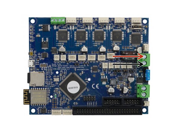
The connectors for the Duet controller are keyed, so there is only one way which they can plug in.
-
For 750x1000mm Screw Drive Machines and 1000x1000mm Screw Drive machines, the Right Y-Axis motor wire may have different wire colors to the other motor wires. This is normal, connect the wires as normal.
-
The Mains Power should remain off during all wiring of the Duet Controller.
-
PSU Cable from Power Supply - Connect Red Positive Wire into the Top Screw Terminal and Black into Bottom Screw Terminal.
-
-
-
Z-Axis Stepper Motor Wire.
-
Left Y-Axis Stepper Motor Wire.
-
X-Axis Stepper Motor Wire.
-
Right Y-Axis Stepper Motor Wire.
-
-
-
Z-Axis Limit Switch
-
Y-Axis Limit Switch
-
X-Axis Limit Switch
-
Fans connected to either of the Always on Fan Terminals.
-
-
-
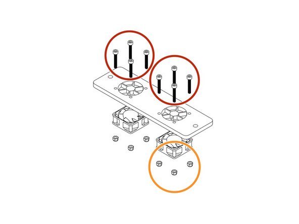
Use 8 x M3 Cap Head 20mms to fix the fans highlighted in Yellow onto the Mount with the Fan label facing outward.
-
Secure the M3 Cap Head 20mm's using 8 x M3 Nyloc Nuts.
-
Thread 2 x M5 55mm Low Profile Bolts through the fan mount.
-
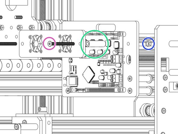
Slide the Aluminium Spacers highlighted in Green over the bolts.
-
Now attach to the Main Board mount using 2 x M5 Nyloc Nuts.
-
Remember to connect the fans to 'Always On' Fan connection of your Duet Controller before tightening the M5 Nyloc Nuts.
-
-
-
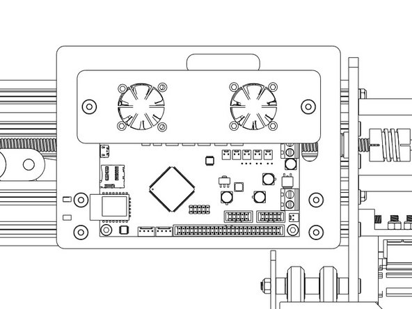
Using the already inserted cable ties fix the wires into place securely to prevent any unnecessary movement and to keep the machine looking neat!
-
If you have the Ethernet version also secure that.
-


Thanks for following the guide. Any issues, please contact us!
Thanks for following the guide. Any issues, please contact us!
Cancel: I did not complete this guide.
22 other people completed this guide.

9 Comments
I Presume The router power Cable is run through the X axis chain and connected to the duet board, I cant find anything telling me how to connect it?
Peter Johnston - Resolved on Release Reply
It's the openbuilds one you sell so its 24v. Is there another output to save me rewiring through the drag chains to main power supply? Cheers
Danny borrill - Resolved on Release Reply
Hi, ok thats fine then, you can connect it to the Duet Always on fan output, no need to go to the PSU.
Is there a terminal to plug a led ring into? Would the other always on fan be enough?
Danny borrill - Resolved on Release Reply