
-
-
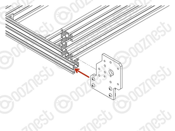
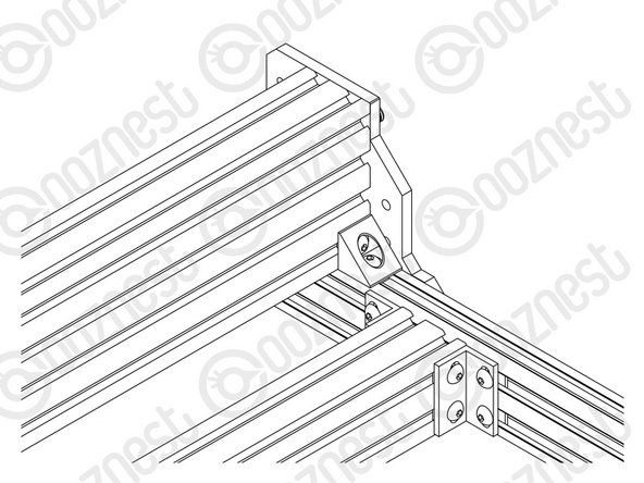
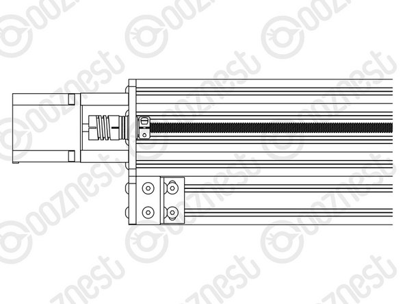
Prepare 2 x Y-End-Plate in the orientation shown in Image 1, with a M5-Button-Head-Bolt-12mm through each of the 4 bottom holes and a M5-Tee-Nut slightly threaded onto each one.
-
The flat side of the M5-Tee-Nut should be facing the Y-End-Plate.
-
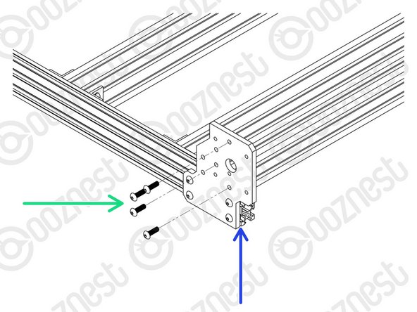
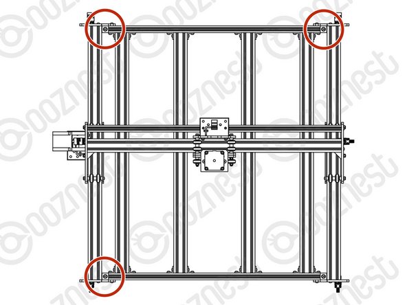
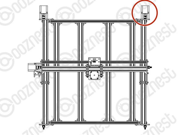
Repeat the above 2 points, but for 2 x Y-End-Plate in the orientation shown Image 2.
-
-
-
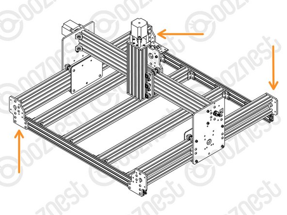
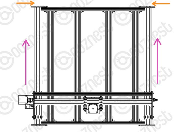
Position the two Extrusion-F's on top of the Base-Assembly.
-
Carefully slide the Y-Carriages on the X-Gantry through the Extrusion-F's
-
Adjust the position of each Extrusion-F so the ends are flush with the corners of the Base-Assembly.
-
-
-
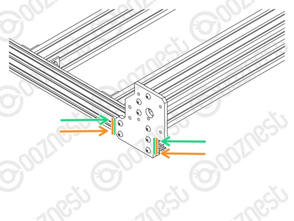
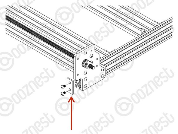
At the front right corner of the machine, slide a Y-End-Plate into the two front-facing slots of Extrusion-A.
-
Attach the Y-End-Plate to Extrusion-F using 4 x M5-Button-Head-Bolt-16mm through the non-threaded holes on the Y-End-Plate and into the threaded holes on Extrusion-F.
-
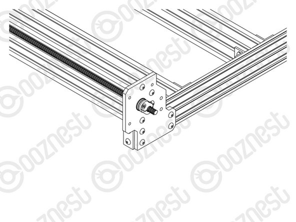
Make sure the side of the Y-End-Plate is flush with the end of Extrusion-A.
-
Then tighten all the M5-Button-Head-Bolt-12mm on the Y-End-Plate.
-
Repeat for the other 3 corners of the machine.
-
-
-
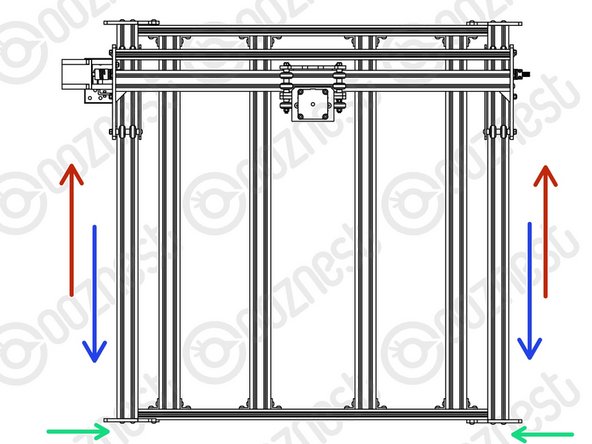
Slide the X-Gantry to the back of the machine as far as it will go.
-
Slightly loosen the 4 x M5-Button-Head-Bolt-12mm on each of the two front Y-End-Plates.
-
Carefully slide the X-Gantry to the front of the machine as far as it will go.
-
Re-tighten the M5-Button-Head-Bolt-12mm loosened in the green point above.
-
Keep the machine at the front and slightly loosen the 4 x M5-Button-Head-Bolt-12mm on each of the two back Y-End-Plates.
-
Carefully slide the X-Gantry to the back of the machine as far as it will go.
-
Re-tighten the M5-Button-Head-Bolt-12mm loosened in the orange point above.
-
Slide the X-Gantry back and forth. It should run smoothly without binding.
Hi I have completed this step but I am unsure how freely the carriage should run. I followed the initial construction steps and tightened the hexentric nuts until there was some friction. I have also reviewed the Eire workshop videos but Tommy is able to push his X carriage along the X axis with very little effort. The initial instruction was to tighten the hexentric nuts until there was friction and all the wheels turned. If I loosen the nuts so that the carriage moves more freely not all the wheels turn and I cannot find a medium between the two. Just for clarity I can move the carriage all along the Y axis without it suddenly stopping or being more difficult to push along - is that OK? Kind regards Kim
Kim Humphreys - Resolved on Release Reply
Hi Kim,
You should be able to turn the wheels with your finger and thumb, To correctly adjust the wheels please do the following:
- Set all the eccentric spacers to their widest position
- Slightly loosen the bolts holding wheels on the aluminium spacer side
- Adjust the eccentric spacers so all the wheels (both sides) are slightly touching the extrusion.
- Tighten the bolts holding wheels on the aluminium space side
- Check the eccentric spacers so all the wheels (both sides) are slightly touching the extrusion.
- As you start using the machine, the wheels "bed in", recheck the eccentric spacers at regular intervals, to ensure the wheels are not too tight or too loose. Repeat the above as necessary.
The carriage sounds like it is moving fine for the binding check, once the motors are assembled the carriage will no longer move freely.
Thanks.
I am getting some binding when pushing gantry back and fourth, any ideas on what the problem may be?
Mathew cox - Resolved on Release Reply
Hi Mathew,
The issue could be that the nut blocks are too tight, and is binding the lead screws. Please undo the bolts on the nuts blocks and tighten the bolts again, but do not over-tighten them.
Thanks.
I found it more convenient to install my router mount (section 7) at this point. I was able to move the X-Gantry toward the front of the machine and install this without having to stretch over the table, or have power on the machine to move the gantry closer.
Tom Hawkins - Resolved on Release Reply
-
-
-
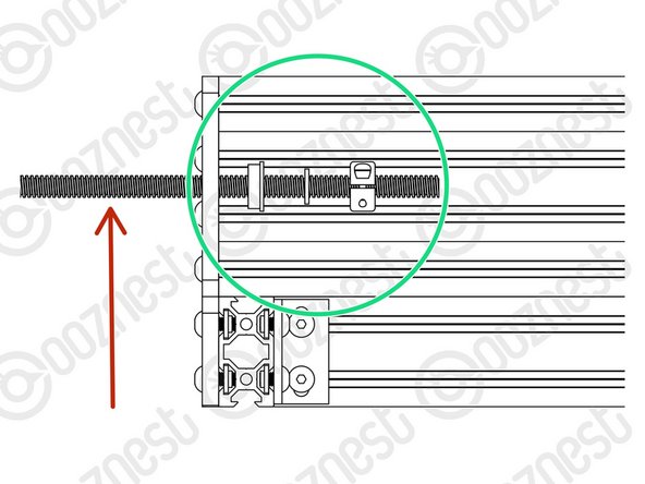
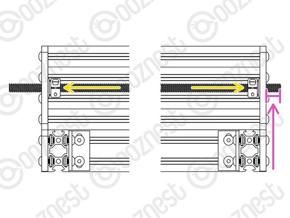
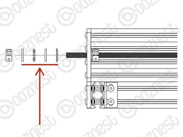
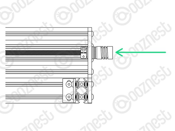
Insert a Lead-Screw-Y through the large 16mm hole on the front right Y-End-Plate so it protrudes into the channel on Extrusion-F roughly 100mm.
-
Slide onto Lead-Screw-Y a Flanged-Radial-Bearing - ->- - Rubber-Bushing - ->- - Clamping-Collar.
-
Insert the Lead-Screw-Y further into the channel, and then thread it through both Nut-Blocks on the Y-Carriage-Right.
-
The Nut-Blocks should be loose so their position can be adjusted to allow Lead-Screw-X to thread through.
-
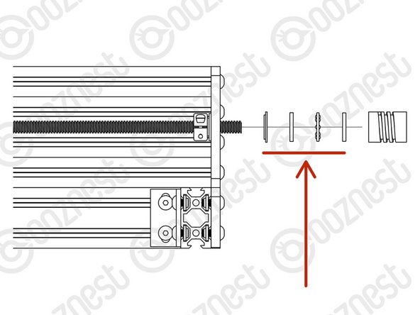
Once through the Nut-Blocks, slide onto Lead-Screw-Y a Clamping-Collar - ->- - Rubber-Bushing - ->- - Flanged-Radial-Bearing.
-
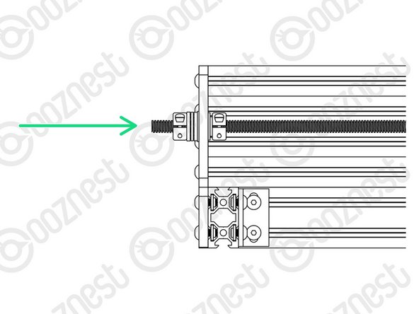
Thread through Lead-Screw-Y further so it goes through the large 16mm hole on the back right Y-End-Plate. Adjust the Lead-Screw so there is 14mm protruding from the back right Y-End-Plate.
-
Seat the Flanged-Radial-Bearings into the Y-End-Plates, slide the Rubber-Bushing against the Flanged-Radial-Bearings and finally slide the Clamping-Collars so they are against against the Rubber-Bushings. Slightly tighten the Clamping-Collars.
-
Repeat all the above points for the left Y-End-Plates and Y-Carriage-Left
The left hand Lead Screw Y was incredibly tight to get in... impossible to do by hand. I managed to do it by using a drill on a low setting, but it's so tight now you can't turn it by hand? I worry this isn't ideal? It didn't look warped but i wonder if it was slightly? I'm a few steps further on now putting the step motors on...
Gareth Simmonds - Resolved on Release Reply
-
-
-
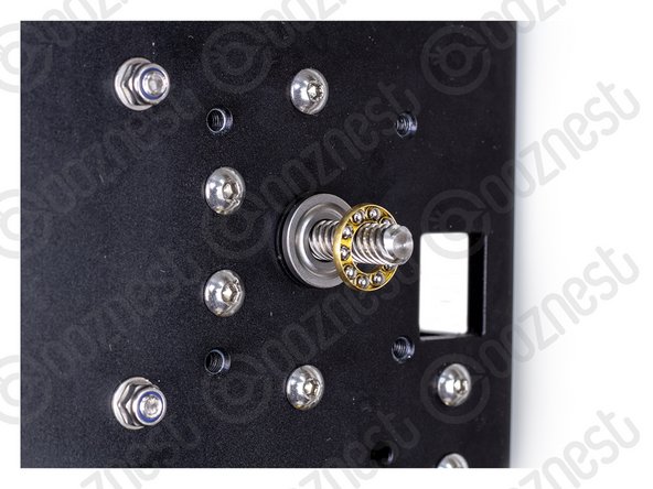
Thrust-Bearings come in 3 parts. Thrust-Bearing-Housing-Washer, Thrust-Bearing-Caged-Roller and Thrust-Bearing-Shaft-Washer
-
The Thrust-Bearing-Housing-Washer and Thrust-Bearing-Shaft-Washer look exactly the same. They are not.
-
We recommend adding a generous amount of bearing Lubricant to the grooved face of both washers.
-
On the Lead-Screw-Y protruding from the front right Y-End-Plate, slide on a Nylon-Shoulder-Washer - ->- - Thrust-Bearing-Housing-Washer - ->- - Thrust-Bearing-Caged-Roller - ->- - Thrust-Bearing-Shaft-Washer
-
The Nylon-Shoulder-Washer seats in the 16mm hole on the Y-End-Plate.
-
The Thrust-Bearing-Caged-Roller seats in the grooves on the Thrust-Bearing washers. Same orientation as before.
-
Finally slide on a Clamping Collar. While pushing the Clamping-Collar against the Thrust-Bearing assembly, tighten the Clamping-Collar.
-
Repeat all the above for the front left Y-End-Plate.
Not sure what the 3rd picture adds in terms of clarity. This is from a totally different part of the build.
David Gracey - Resolved on Release Reply
Was thinking the same until I realised,the following...that picture is showing the proper orientation of the "thrust bearing caged roller". There is a difference to either side of the "thrust bearing caged roller".
Hello. Are the trust bearing need to be greased after installing?
Luis Montano - Resolved on Release Reply
I found one of my lead screws to be a bit tight as well. I loosened the nut blocks a tad, and that released enough friction that it moves freely now. Is this okay or will it cause issues later?
Hi Brian,
If you run the machine with one loose for a small amount of time, it should ‘bed’ in and find its natural position, then it can be tightened.
Robert
Robert -
I have one lead screw y that turns freely and the other one is tight, it seems to be binding on the plastic blocks, any tips to rectify this?
Rob Thompson - Resolved on Release Reply
Rob!
Check if one of your nut blocks is incorrectly drilled. My lead screw hole was drilled with offset which made it bind. View from the side if you have a gap or if the hole is offset to the wrong side.
Emil -
Hi Rob, If you find one is binding please double check it on the other Lead-Screw by hand to see if it is tight as it should turn freely.
Should it bind on the other Lead-Screw please get in touch here - https://ooznest.co.uk/help/#tab_technica... then we can arrange a replacement for you.
-
-
-
On the Lead-Screw-Y protruding from the back right Y-End-Plate slide on a Nylon-Shoulder-Washer - ->- - Thrust-Bearing-Housing-Washer - ->- - Thrust-Bearing-Caged-Roller - ->- - Thrust-Bearing-Shaft-Washer
-
The Nylon-Shoulder-Washer seats in the 16mm hole on the Y-End-Plate.
-
The Thrust-Bearing-Caged-Roller seats in the grooves on the Thrust-Bearing washers. Same orientation as before.
-
Finally slide on a Flexible-Coupler. While pushing the Flexible-Coupler against the Thrust-Bearing assembly, tighten Flexible-Coupler
-
On the Flexible-Coupler tighten the clamping bolt first and then the grub screw.
-
Repeat all the above for the back left Y-End-Plate.
The last of my Thrust-Bearing-Shaft-Washer will not fit over the lead screw (rather typically the last one) - I've tried it in other positions and it won't fit onto the end of any of the lead screws - is there anything I can do for it?
Hi after i installed the thrust bearing at the back there was only 5.7 mm for the flexible coupler to sit on the lead screw . Is that enough
Attie Engelbrecht - Resolved on Release Reply
Hi Attie,
If the length protruding without the thrust bearing is 14mm, then that is correct.
Robert -
-
-
-
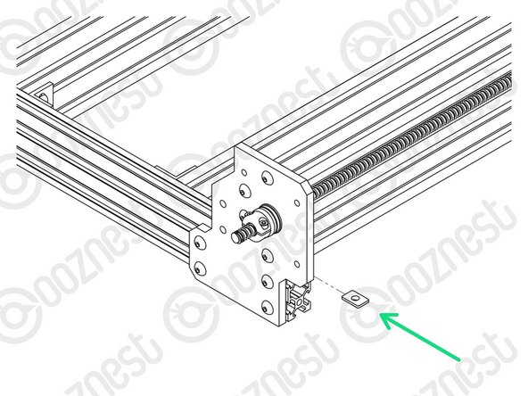
At the front right corner of the machine, an Angle-Corner goes in the corner between Extrusion-A and Extrusion-F.
-
First slide an M5-Tee-Nut into the top slot of Extrusion-A.
-
The flat face of the M5-Tee-Nut should be facing upwards.
-
Use a M5-Button-Head-Bolt-8mm and the previously inserted M5-Tee-Nut to attach it to Extrusion-A.
-
To attach it to Extrusion-F, use a M5-Button-Head-Bolt-8mm and M5-Drop-In-Tee-Nut.
-
M5-Drop-In-Tee-Nuts do not need to slide in from the end.
-
They go in to the slot parallel, when the bolt engages they should spin perpendicular to the slot and bite into the underside of the slot.
where in this instruction was it to put m5 t nut holder things in the c channel before attaching the end plate? I have been taking this really slowly and I’m not seeing it! I really don’t want to take it apart now I’ve put all the other pieces on!
rgadsby2012@gmail.com - Resolved on Release Reply
In this step you need 4x M5-Drop-In-Tee-Nuts for the corners but in the next part of the guide when assembling a Router Clamp you need 8x M5-Drop-In-Tee-Nuts, however the package came only with 10x M5-Drop-In-Tee-Nuts. Did I miss something or am I 2x M5-Drop-In-Tee-Nuts short?
Patrick Puolakka - Resolved on Release Reply
Hi Patrick,
The main Workbee kit comes with 50x M5 Drop Tee Nuts. The Router Mount box will contain a further 10x M5 Drop Tee Nuts. Giving you a total of 60x. I hope this clarifies things?
Thanks.
The instruction for step 8 states that it is extrusion F but is indeed Extrusion E.
Richard Jackson - Resolved on Release Reply
Hi Richard,
As you have the 1500x1500 Workbee, your extrusion F and E will be the same size. Extrusion E is used for the X-Gantry.
Thanks
Once I got to this stage of the build I had no idea which extrusion was which (i.e. A, E) as I’ve removed the labels. Might be worth adding a callout somewhere not to remove the labels until the end? Either that or name them in the diagrams.
It might be worth noting, as there isn’t a diagram, that the drop-in tees go in with the collar facing out, which is the opposite of the way the tee-nuts go in. There is a picture in the next guide that shows this.
Philip Davidson - Resolved on Release Reply
Rrrrrrrrrrraaaaaaaahhhhhhhhhhh!!
Wish I’d read this before I walked away and kicked the cat and kid and then got an earful from the missus
I read this way too late, needs an update in the guide. spent over an hour trying to get these 4 tee nuts to do as described. Thanks Philip
When do we tighten the Nut-Blocks from Assembly 2, step 01 and Assembly 3, step 4?
Mark Williams - Resolved on Release Reply
Hi Mark,
They are tightened in the testing guide, don’t tighten them until that guide.
Robert
Robert -
-
-
-
Repeat the previous step for the other 3 corners.
-
Double-check the M5-Drop-In-Tee-Nuts are correctly engaged with Extrusion-F.
-
-
-
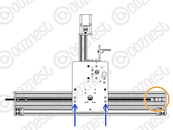
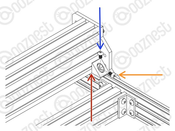
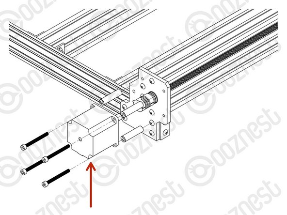
Attach a Stepper-Motor to the threaded holes on the back left Y-End-Plate using 4 x M5-Cap-Head-Bolt-50mm and 4 x Aluminium-Spacer-40mms.
-
Orient the Stepper-Motor so that the wire is facing down.
-
The shaft of the Stepper-Motor goes into the Flexible-Coupler.
-
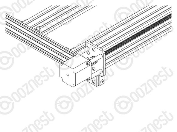
On the Stepper-Motor side make sure the Flexible-Coupler grub screw is on the flat portion of the Stepper-Motor shaft.
-
Once in position, tighten the clamping bolt first, then the grub screw.
-
The Lead-Screw side was tightened earlier in this guide.
-
-
-
Repeat the previous step for the right Y-Axis Stepper-Motor.
-
-
-
Attach an End-Cap to the front left end of Extrusion-A using 2 x M5-Button-Head-Bolt-8mm.
-
Repeat this for the other 3 bare ends of the Extrusion-A's.
-
-
-
Wow, what a difference. The machine can stay where it is now, we are going to be adding more stuff on!
-
Guide Complete - Proceed to 7. Router Mount
I have reached the end of this guide and realized i have attached the stepper motors on the wrong side, Is this a problem or do they need relocating?
James Hall - Resolved on Release Reply
-


Thanks for following the guide. Any issues, please contact us!
Thanks for following the guide. Any issues, please contact us!
Cancel: I did not complete this guide.
74 other people completed this guide.

9 Comments
Very impressed with the quality of the components, excellent instructions, I like the components being in very well labelled bags. I am slowly and meticulously working through getting each part out as I get to them and returning bags to correct boxes when I have finished a section. I suspect I am benefiting from others comments being implemented. Really enjoying the process and so far it all seems to move smoothly and is square to the mm. Here’s to the next stage. Thank you.
(second part of my comment, but why require/demand to be signed in, welcome ALL comments)
……….would have been much better and would have saved time. Then…. it would be good to describe the sections a bit more in the overview. Then the extrusion numbering: you have to remove the labels printed on them as all are in the way except the short extrusion D for the Z-axis. Many times I am was wondering where extrusion A, B, E or F actually were. Another issues: the glue of the labels is super hard to remove, even with alcohol or aceton; you really have to use a label glue dissolvent to remove it.
But my machine Z+ 1500x1500 is no fully assumbled apart from the table below it and it all seems to work fine sofar. It’s for me the first time I do this, although my experience with 3D printers and Fusion360 comes in handy as it is not really so far apart.
Greetings,
Mark Wiersma
Mark Wiersma - Resolved on Release Reply
Hi Mark,
Thanks for your comment. The maximum comment length is set by Dozuki (The software behind learn.ooznest.co.uk) and we have no control over it I am afraid.
The same applies to having to be logged in to comment (On Prusa manuals you need to be logged into to comment also)
I believe Prusa uses the same software for their guides.
I have looked at Prusa guides and can see they have steps about collecting the parts, which is a good idea, and something we can think about adding.
Did you see our Box Cheat Sheet here to help locate the parts: https://ooznest.co.uk/wp-content/uploads...
For the extrusion, the labels should have been peelable, I have raised this as an issue, as to why they are not peelable, as I know we have specific labels for the extrusions that should come off easily. My apologies they were difficult to get off in your case.
Thanks for all your other points, they have been noted.
Robert
Robert -
Hi Robert,
Just a general comment on the assembly manuals: it’s doable and besides some small typos it is all clear. But if I compare it to the assembly instructions of the Joseph Prusa 3D printer it is not as good. What would save the assembler time and avoid making mistakes would be for instance briefly summerizing which parts, screws, bolts or whatever is needed instead of mentioning this within the assembly instructions, including a small graphic image of the parts. Collecting the parts is time consuming , as the plastic bags are white the side where the description of the content is and transparant on the other side. I noticed in some videos of older machines that you used to use transparent plastic bags labelling it with a sticker. This …… (why limit these comments, I don’t get it…..)……
Mark Wiersma - Resolved on Release Reply
Excellent instructions for such a complex bit of kit. I, however get a little confused with reference to front and back of components / machine. Fantastic otherwise.
Absolutely the same issue, the front and back changing every other instruction meant i initially place the gantry on backwards. More wide shots needed in instructions for reference!
Ian -
Perform step 2 before step 1! Otherwise you need to balance the F-extrusion while preparing the Y-end-plates!!!
Emil - Resolved on Release Reply
Hi Emil,
Good point. I have swapped the steps over based on your suggestion.
Robert -