
-
-
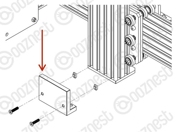
Attach the Z-Bracket to the Router-Clamp using 3 x M8-Cap-Head-Bolt-8mm. (Please note in your kit these may be M8-Cap-Head-Bolt-10mm)
-
-
-
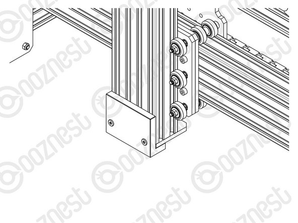
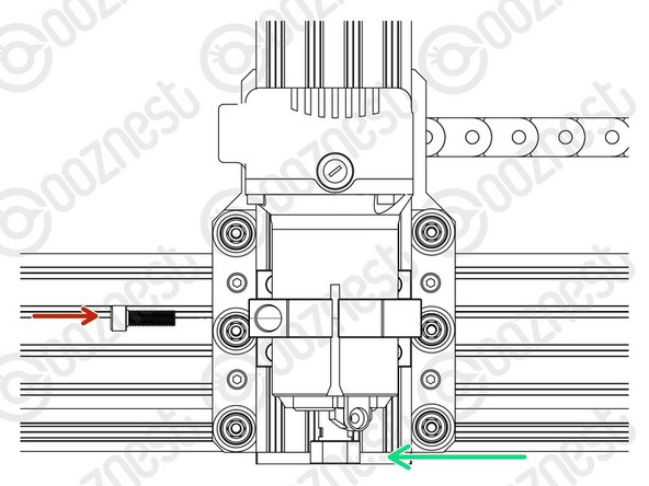
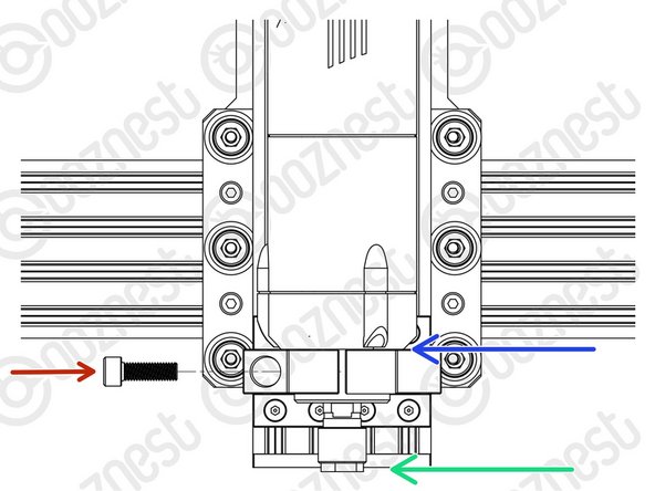
Insert 8 x M5-Button-Head-Bolt-12mm through the Z-Bracket.
-
Slightly thread a M5-Drop-In-Tee-Nut on to the end of each bolt.
-
-
-
Reference the correct face of the Height-Reference-Tool for your Router Head.
-
50.00mm - WorkBee Router Head/Katsu/Makita/DeWalt Routers.
-
17.60mm - Mafell/Kress/Festool Spindles.
-
Attach the Height-Reference-Tool to the bottom of Extrusion-D using 2 x M5-Button-Head-Bolt-12mm and 2 x M5-Drop-In-Tee-Nuts.
-
The Height-Reference-Tool should be pushed up as high as possible.
-
Do not over-tighten the 2 x M5-Button-Head-Bolt-12mm.
-
The Height-Reference tool will be removed later.
-
-
-
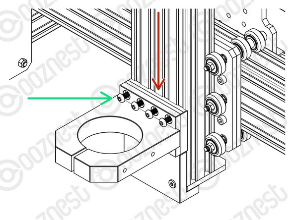
On one face of the Router-Clamp there are 4 threaded holes. These should be face down.
-
Sit the Router-Mount-Assembly on top of the Height-Reference-Tool.
-
Fix the Router-Mount-Assembly to Extrusion-D.
-
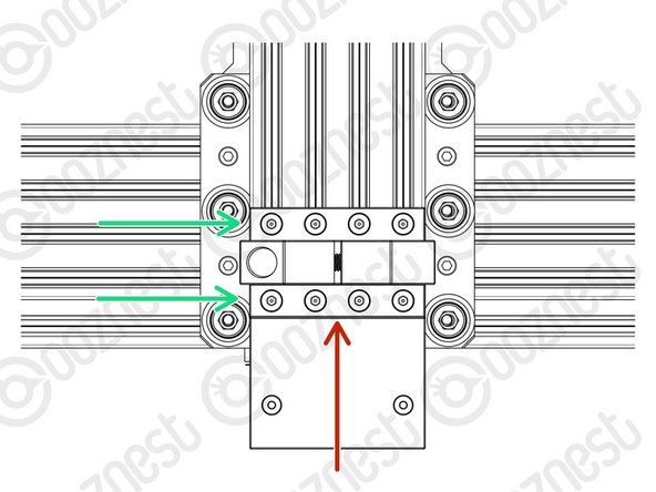
Tighten the 8 x M5-Button-Head-Bolt-12mm inserted previously.
-
Make sure M5-Drop-In-Tee-Nuts are engaged with the slots on Extrusion-D.
-
Remove the Height-Reference-Tool.
-
The Height-Reference-Tool is no longer needed.
-
But it can come in handy. It has an etched ruler to measure end mill stick out.
-
-
-
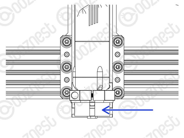
Insert the Router Head into the Router-Clamp and tighten the clamp using the M8-Cap-Head-Bolt-25mm.
-
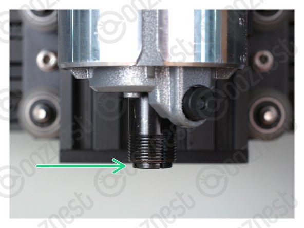
For WorkBee Router Head/Katsu/Makita/Dewalt Routers position it with the collet flush with the bottom of the Z-Axis.
-
For Mafell/Kress/Festool Spindles position the body flat on the top of the Router-Clamp.
-
Do not overtighten the Router-Clamp.
-
It should be tightened no more than the point that the Router Head can no longer be rotated by hand.
-
Any tighter and you will run the risk of pre-maturely wearing the brushes of the Router Head.
-
The power wire of the Router Head should run vertically up to the ceiling. If you have a Dust Shoe, it can be clipped to the extractor hose.
-
Do not put the power wire inside the drag chains of the machine. It is a high power wire and should not run alongside the other wires.
-
-
-
When using the Dust Shoe, please make sure there is adequate strain relief on your extractor hose. If there is no strain relief, it will break the extractor port on the Dust Shoe.
-
Dust-Shoe-Adaptors will be included in the 65mm (WorkBee Router Head/Katsu/Makita) and 43mm (Mafell/Kress/Festool) versions of the Router Mount.
-
WorkBee Router Head/Katsu
-
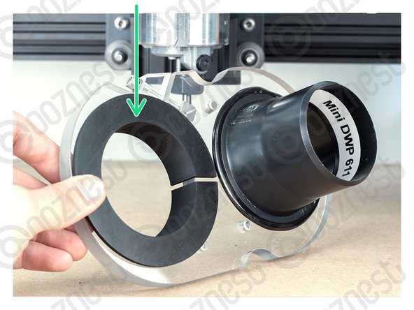
The 65mm Dust-Shoe-Adaptor sits inside the Dust Shoe. The Dust Shoe is then clamped around the body of the Katsu/Makita Router.
-
Mafell
-
This should only be installed if you have a Dust Shoe.
-
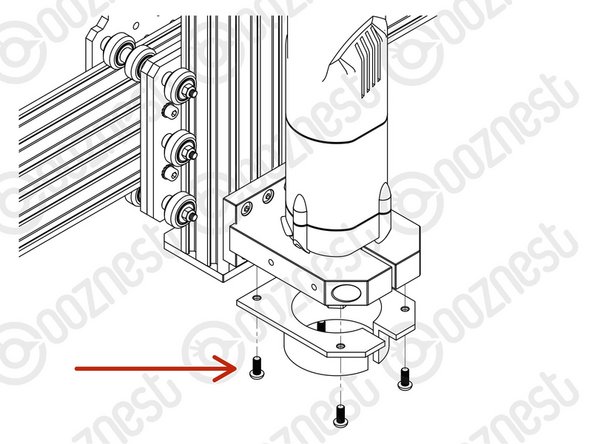
Attach the 43mm Dust-Shoe-Adaptor to the underside of the Router-Clamp using 4 x M5-Button-Head-5mm Bolts.
-
The Dust Shoe clamps around the circular portion of the 43mm Dust-Shoe-Adaptor.
-
-
-
The Mafell FM 1000 is broken in by the Manufacturer so is ready for use.
-
For the WorkBee Router Head/Katsu, we recommend running it at a medium RPM, with no load, for 30-60 minutes.
-
Remove the collet and nut while doing this so it does not come off.
-
-
-
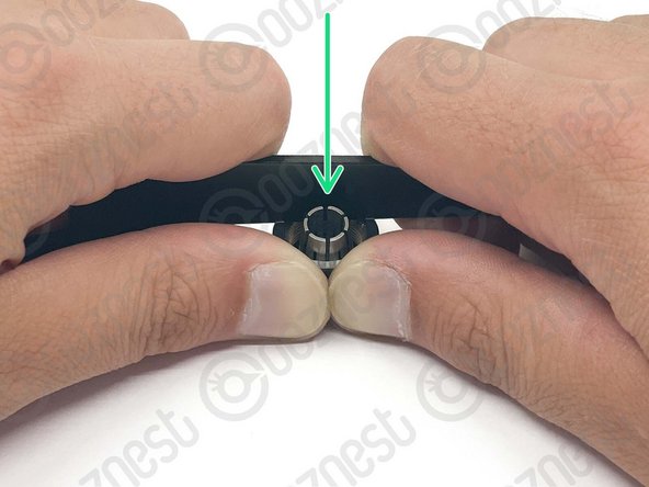
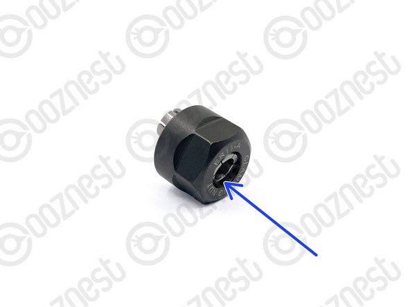
The collet must always be inserted into the nut before attaching it to the WorkBee Router Head or inserting an endmill.
-
Place the collet into the nut and then turn it upside down onto a hard surface.
-
Apply downward pressure to the rim of the nut until it clicks into the retaining ring on the nut.
-
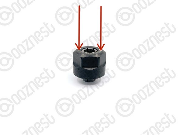
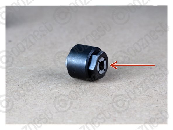
To remove the collet apply a horizontal force to the collet until it clicks out of the retaining ring on the nut.
-
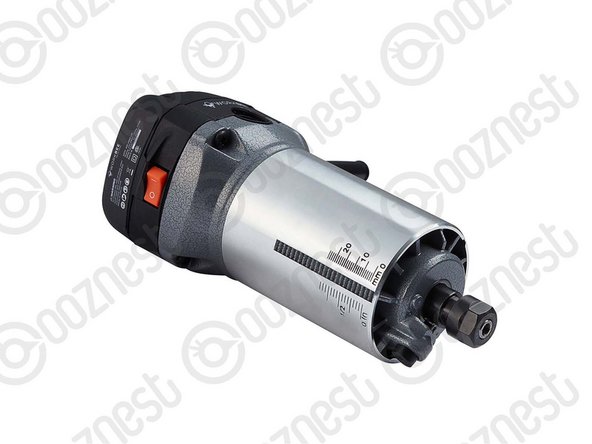
Use the wrench provided with the WorkBee Router Head to get more leverage as demonstrated in Image 2.
-
Push the collet out of the nut on the side which has been released from the retaining ring.
-
Each collet can clamp -0.5mm below its rated size. For example, the 1/4" collet (6.35mm) can clamp down to 5.85mm.
-
-
-
Always use the correct collet size for the cutter.
-
Mafell
-
Click the collet into the nut first, then insert the end mill fully.
-
Fix the collet with a maximum torque of 10-11Nm. Tighten the collet by hand, then a 1/8 turn with a spanner, this should be about right.
-
Keep the collet lubricated with a solid lubricant (e.g. Molykote P-40) or by lightly greasing.
-
Katsu
-
Push the collet into the shaft and then the nut over it. The end mill can then be inserted fully.
-
Only use the button on the side to hand tighten the collet. To fully tighten, use two spanners, a 13 spanner on the flat portion of the shaft, the included 22mm spanner on the collet nut.
-
-
-
Starting to look like a CNC Machine now. Now we begin the electrics.
-
Guide Complete - Proceed to 1. Drag Chains
-


Thanks for following the guide. Any issues, please contact us!
Thanks for following the guide. Any issues, please contact us!
Cancel: I did not complete this guide.
62 other people completed this guide.

3 Comments
Total newbie here... I understood step 8 like you had to press the collet through, and free of the nut. But the nut and collet was already correctly inserted into each other when delivered (for the mafell). I managed to apply a lot of pressure with extra tools before realising what was wrong. Thanks for a great guide though.
Best regards Søren
Søren Storm - Resolved on Release Reply
Apologies, I had a small issue with the reference gauge and then forgot to follow it up. Life complexity got in the way. The bottom plate is fixed to extrusion D by protruding bolts. For the Mafele router this does not allow the height reference tool to sit against the bottom plate or give the cam nuts the space to locate in the face of extrusion D . I have taken pics of the situation but i am not sure now where to send them. The router was easily fixed in place level, and at correct height, using a custom made L section bit of hardwood. Couple of mins on the table saw. The workbee is now finished and running ( I love it and really enjoyed the build) but I need a bit of chat about the code my post outputs and its interaction with the workbee controller.
Frank Triggs - Resolved on Release Reply
Hi Frank,
Thanks for the pictures you emailed to us. I think it is because the z-plate is round the wrong way. The z-plate on one side has counter-bores for the heads of the bolts to sit in.
Robert
Robert -