
-
-
With one of Y-GT3-Timing-Belt-1m inserted previously wrap one end around a Belt-Tensioner as shown. The best method is to go up, over, and then back onto itself so that the teeth engage with each other.
-
Secure using a Cable-Tie-Small, going around both sections as close as possible to the Belt-Tensioner. Cut the excess belt off - a couple of teeth from the Cable-Tie-Small.
-
Next, using a M5-Low-Profile-10mm attach the Belt-Tensioner to the threaded hole on the Y-End-Plate at that end of the belt. Only screw this bolt in two full turns, as this will be used to tension the belt later.
-
Ensure the Tee-Nut inserted in 5. Base Assembly, Step 2, is underneath the hole on the Belt-Tensioner.
-
Repeat for the the other end of the Y-GT3-Timing-Belt-1m, however this time you need to pull through as much excess belt as possible, before wrapping it around the tensioner.
-
To gauge where the Belt-Tensioner needs to go on the belt, put the belt tensioner in the same position as if doing Step 1 above, then pull the belt along the extrusion.
-
Then roughly mark where it reaches the slots on the belt tensioner. Then continue with Step 1, wrapping it around at the point marked.
-
-
-
Repeat Steps 1 for the other Y-GT3-Timing-Belt-1m on the Y-Axis.
-
In 3. X-Carriage Assembly, Step 4, the GT3-Pulley was attached to the X-Axis NEMA23-Stepper Motor but not secured. Secure it now so that the toothed section of the GT3-Pulley is centred with the back slot of the C-Beam-750mm.
-
Repeat Steps 1 for the X-GT3-Timing-Belt-1m, this has not been inserted yet, so first wrap it around the GT3- Pulley and under the wheels each side as shown.
-
-
-
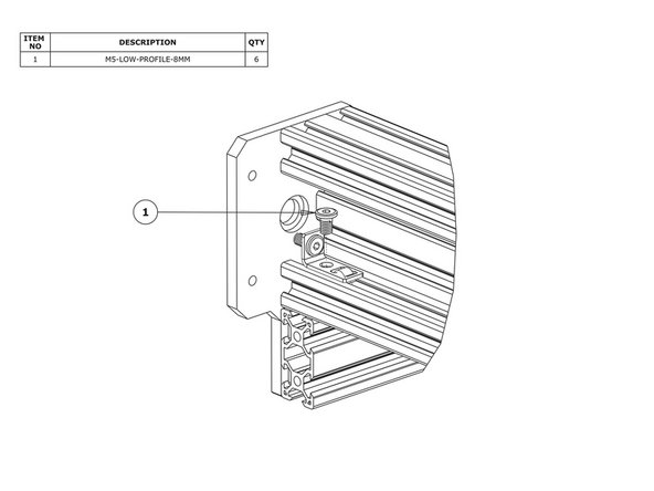
For one of the Y-Axis belts, screw a M5-Low-Profile-8mm bolt through the belt tensioner and into the Tee-Nut, positioned in Step 1. Do not tighten it.
-
Do this for both Belt-Tensioners on this axis.
-
The M5-Low-Profile-10mm bolts in Step 1 are used to tension the belt. The exact tension needed is hard to explain, but if it is too loose the machine could skip steps and it won’t be accurate.
-
Too much and it risks bending the motor shaft or causing premature wear. It should be tensioned enough so that the belt is just on the point that it can be plucked with an audible tone. At this point do not add anymore tension.
-
Please see this video here for info on belt tensioning: https://www.youtube.com/watch?v=-FHBeNOo...
-
Once happy, tighten the M5-Low-Profile-8mm bolts in Step 4, as these will hold the tensioner in position. Check that the axis still runs freely with light-moderate force, and there are no bite points.
-
If there are, this is most likely a result of the GT3-Pulley being out of alignment with the center of the track. This would need to be checked and adjusted.
-
Repeat Step 4 for the other two belts.
-
-
-
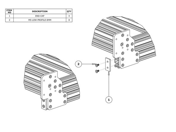
Attach an End-Cap to front left end of the V-Slot-2040-745mm using 2 x M5-Low-Profile-8mm bolts.
-
Repeat this for the other 3 x End-Caps on the other bare ends of the V-Slot-2040-745mms.
-


Thanks for following the guide. Any issues, please contact us!
Thanks for following the guide. Any issues, please contact us!