
-
-
This step requires the removal of existing parts on the Z-Axis Stepper-Motor
-
Remove the left 2 x M5-Cap-Head-Bolt-50mm.
-
Slide out the 2 x Aluminium-Spacer-40mms.
-
-
-
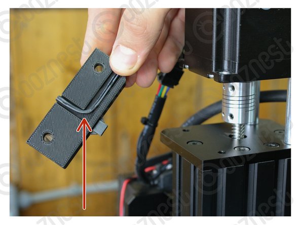
Insert the 2 x Aluminium-Spacer-35mm into the Touch-Probe-Mount, pushing them in until they can go no further.
-
-
-
Tuck the wire underneath the Touch-Probe-Mount as seen in Image 1.
-
Place the Touch-Probe-Mount with the 2 x Aluminium-Spacer-35mm under the Z-Axis Stepper-Motor.
-
Using the previously removed 2 x M5-Cap-Head-Bolt-50mm secure the Stepper-Motor.
-
-
-
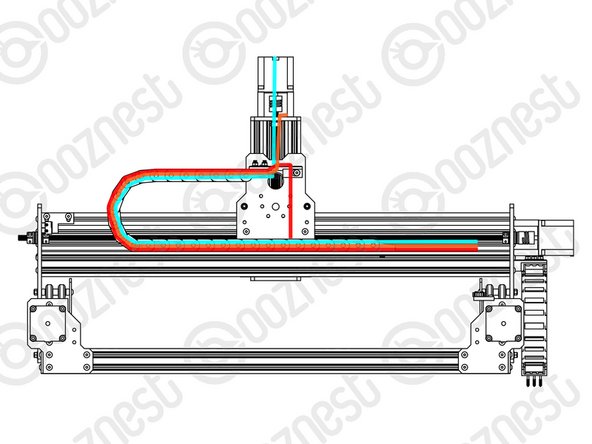
Feed the Touch Probe Wire through the Drag-Chain-Mount and then through Drag-Chain-X so it comes out the Fixed End.
-
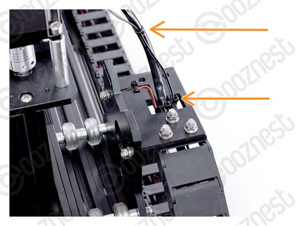
Secure the wire to the Drag-Chain-Mount using a small cable tie. Then secure it along Motor-Wire-6.
-
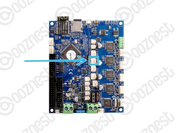
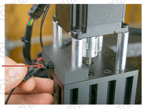
The connector on the wire is keyed, so there is only one way which it can plug in.
-
Plug in the Touch Probe Wire following Image 2.
-
-
-
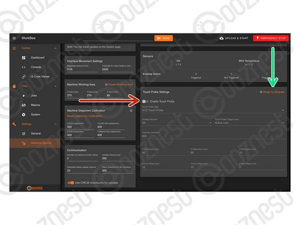
Enable The Touch Probe.
-
Press 'Reset to Defaults' to make sure we have the correct settings for the Original WorkBee XYZ Touch Probe.
-
-
-
Plug your Touch Probe into the Touch Probe Mount Connector.
-
In WorkBee Control go to Control > Dashboard.
-
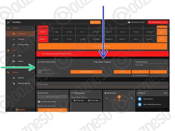
You will now see the panel 'Touch Probe Control'
-
You can view the status of the Touch Probe.
-
Clip the Crocodile Clip to an End mill not in the Router Head, and hold it touching the Touch Probe like Image 3
-
The status of the Touch Probe should change to 'Triggered'
-
If it does not, verify your wiring. Otherwise Contact Us.
-
-
-
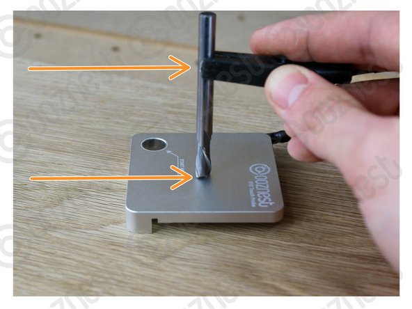
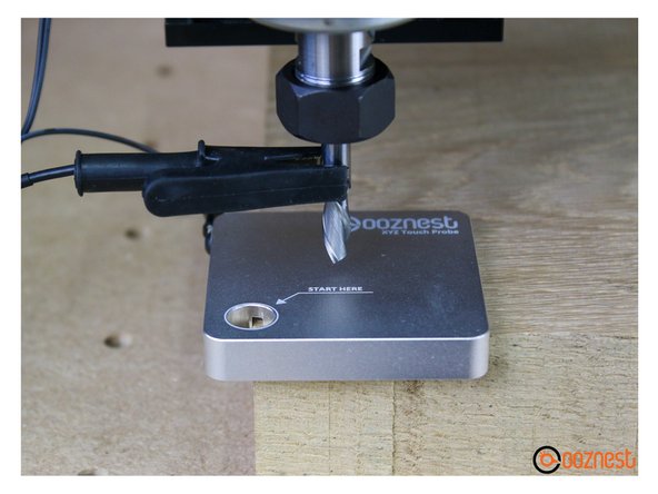
Locate your Touch Probe over the corner of the material. Jog the machine until it is within the 'START HERE' Hole, roughly level with the surface of the Touch Probe. Connect your End mill.
-
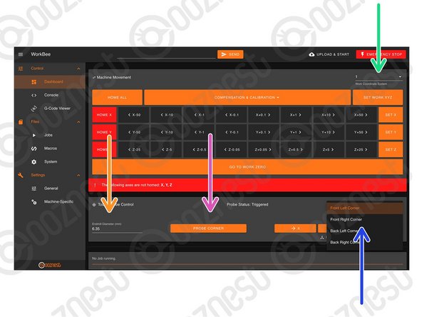
Select the Work Coordinate system you would like to probe in.
-
Select the Corner you have the Touch Probe on.
-
Define the Endmill Diameter.
-
Press Probe Corner to begin probing.
-
Wait until the 'Probe Successful' confirmation.
-
Unclip the Touch Probe from the End mill and Touch Probe Mount.
-
Press 'Go to Work Zero'. Your machine should be perfectly aligned with the corner of the material.
-
-
-
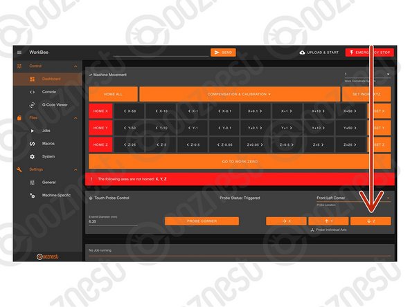
Follow these Steps to Probe the Z-Axis Only.
-
Connect your Touch Probe and End mill like previous.
-
You can either have the Touch Probe on a corner with the End mill over the middle of the probe like Image 1.
-
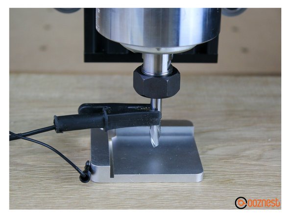
Or you can have the Touch Probe anywhere on your material, but upside down with the End mill over the inset portion like Image 2.
-
This time just press the Probe Z button.
-


Thanks for following the guide. Any issues, please contact us!
Thanks for following the guide. Any issues, please contact us!
Cancel: I did not complete this guide.
45 other people completed this guide.

23 Comments
Hi, just setting up the touch probe. However, I am using the black box. The box has a probe space and a three wire connector, as the probe is only two wire, can I just confirm I need to wire power and signal and leave ground blank? Thanks. Mick
Hi Mick,
The Ooznest XYZ touch probe operates like any other Normally Open Touch Probe so it would connect in the same way as a Z Touch Plate. Connect the 2 cables to the GND and SIG, leaving the middle empty, as per this image: https://docs.openbuilds.com/doku.php?id=...
Thanks.
Hi Graham,
The touch probe does require some space around it to be able to move and check the X&Y, is your material very close to the front left of your working area? Can you push the material back and to the right further?[br]
You can also set the XYZ without the touch probe, following step 5 here: First Project
Thanks
Hi Ryan
I have had my 1500 x 1500 machine working and realized that to cut the larger sheets and set a larger working are i needed to update my firmware. Before i did the update the xyz probe worked fine and could could cut small sheets without problems. After the update it will only detect the Z axis and then shows an error . If i try manually to probe it fails and does not clear the probe.
Do i have to manually create a macro to now perform the action needed? If i try to manually set the machine to work zero it still shows an error an shows ( cutting outside of machine perimeters)
Im only trying trying to cut 1220mm x 1220mm
Thanks
Graham
Hi Ryan
I have a 60 Deg bit how do you probe the corner , when i tried it the bit gos half way down the angle only so gives an incorrect centre.
Thanks Glen.