
-
-
The manual is broken down into sections: Mechanical Assembly, Electronics Assembly, Connecting and Testing.
-
Connecting is broken into two sub sections - Connect Via Wifi and Connect Via Ethernet.
-
Only follow the sub section matching the connectivity of your machine.
-
For the Ethernet version, you do not need to connect via USB.
-
Within each section follow through the guides in numerical order.
-
-
-
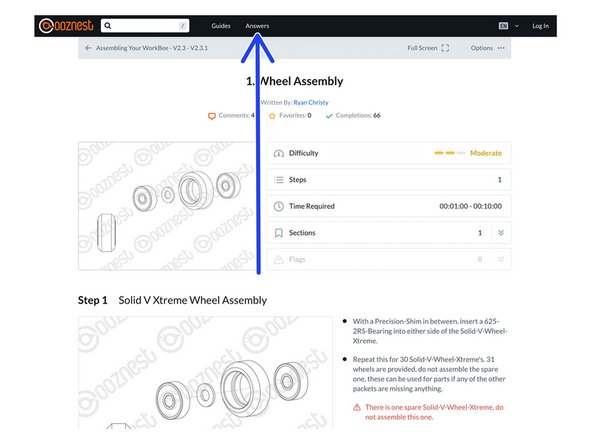
Each Guide is broken down into a number of Steps.
-
Each Step is broken down into a number of coloured Points.
-
Complete all Points in each Step, and all Steps in each Guide to complete the Guide.
-
Some Steps/Points may not apply to your version. It will be clearly indicated to which version they apply.
-
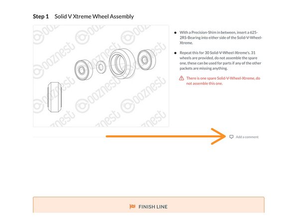
Each Step will have one or more image.
-
Click on the image to view the high resolution version.
-
Try it now!
-
Go to 'Options' > 'Download PDF' to get a printable version of each guide.
-
-
-
1.5, 2.0, 2.5, 3.0, 4.0, 5.0mm Hex keys
-
5.5, 7.0, 8.0mm Spanners
-
Selection of Philips and Flathead Screwdrivers. Pozi #1 & Pozi #2 required. Insulated versions should be used on electronics
-
Engineers Square
-
Soft mallet or Rubber hammer
-
Tweezers and Wire cutters
-
A bearing lubricant such as SuperLube Grease
-
Do not use power tools to assemble the WorkBee Z1+
-
-
-
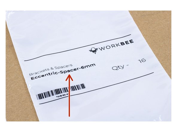
Most parts of the kit are labelled with the part name and quantity provided.
-
The name on the label will match the name used in the guides.
-
For most small parts we will provide spares.
-
The quantity on the label will include any spares.
-
To quickly find which parts are in which box Download and print our Box Cheat Sheet
-
-
-
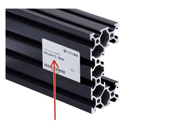
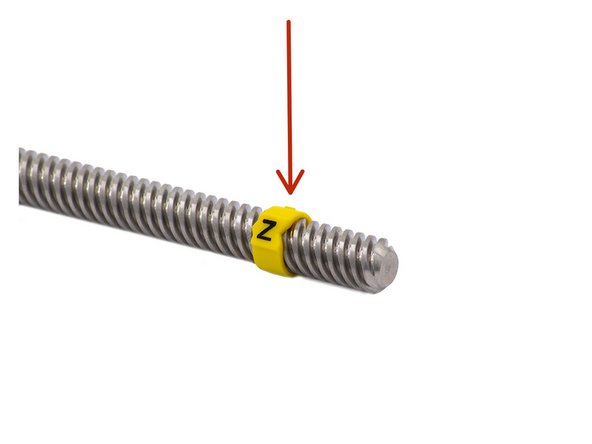
Each Extrusion or Lead-Screw is assigned a letter.
-
In the Guide these will be referred to as Extrusion-A, Extrusion-B, Lead-Screw-Z etc
-
Extrusion-F and Lead-Screw-Y are matched pairs. Do not mix these with other Extrusions or Lead-Screws
-
We recommend that the labels are not removed until the build is complete, as the guides will refer to these letters throughout.
-
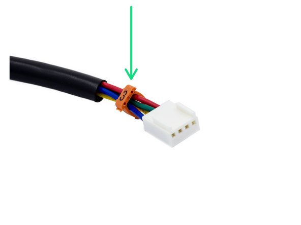
The wires coming from each Motor or Limit Switch will be assigned a Number & Colour based on the Axis they are used for.
-
In the guides, these will be referred to as Limit-Switch-0, Motor-Wire-3, Motor-Wire-4 etc
-
Download and print our Motor Wire and Limit Switch Cheat Sheet
-
-
-
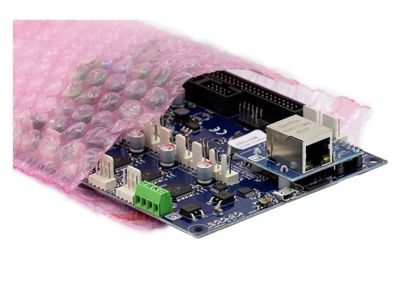
Electronic Boards will come in an ESD Bag.
-
Do not take the Electronic boards out of the bag until needed.
-
Touch something metal before touching the board to discharge any static electricity.
-
Never touch the components on the board. Always handle the board via the edges.
-
Be extra cautious when you are around static materials, such as carpets and wool.
-
-
-
If you are using a USB to Ethernet adaptor it must have crossover detection.
-
Not all USB to Ethernet adaptors have this feature. So double check your model.
-
We sell a tested USB to Ethernet Adaptor on our Website
-
-
-
Read each guide from start to finish before beginning. This will give you an idea of the direction you are heading.
-
Don't just look at the pictures. The written instructions are as concise and cleary written as possible.
-
Follow these guides only! Do not follow other WorkBee build guides or YouTube videos. Do not even follow Ooznest's videos. They may not apply to your version.
-
Everything should go together easily. If something is requiring a lot of force. Take a breather and read the guides again.
-
M5-Tee-Nuts have to be inserted from the end of the extrusion. If you forget to insert one don't panic!
-
Spare M5-Drop-In-Tee-Nuts are provided. Simply drop them in the slot, engage the bolt, and they will bite into the underside of the slot.
-
Don't Rush! Building the WorkBee is as much fun as using it. The quicker you build it the less fun you will have :)
-
You are ready to begin! Start with 1. Wheel Assembly
-


Cancel: I did not complete this guide.
85 other people completed this guide.

4 Comments
Hi I am considering purchasing one of your cnc machines in the near future.I already have a small Dewalt router would this fit to your router mount okay ?…..thanks.
Geoffrey Wilson - Resolved on Release Reply
Hi Geoffrey,
Great to hear you are interested in our machine!
What model is it? If it is a D26200, then it will fit.
Thanks!
Robert -
1mm hex key? The smallest metric size I believe is 1.5mm, then there some weird sizes like 1.3 and 0.9. I have searched my usual tool suppliers but none have 1mm hex keys. So I hope you have some suggestion as to where I could purchase this before I start my build.
Xander Langschmidt - Resolved on Release Reply
Hello Xander, Thanks for spotting this!
I have updated the guide it should be 1.5mm the smallest needed for the flexible coupler grub screws.