
-
-
We recommend that you read through the whole manual before beginning the build, as this enables you to get a rough idea of how it all goes together.
-
Work through all categories and guides in numerical order. If a category or guide has the same number, you only need to complete one of them based on the machine you bought or assembly preference.
-
Before starting each step make sure you have studied the diagram and fully understand what you are doing.
-
When attaching parts, make sure they are properly squared and aligned, and everything should easily fit together. If a part is requiring significant force to attach, stop, take it off, re-read the instructions, and try again. Do not over tighten bolts, as you may strip the threads.
-
If you forget to insert a Tee-Nut when instructed, there is no need to undo any of the work you have done. We have included spare M5-Drop-In-Tee-Nuts in the kit for this situation.
-
M5-Drop-In-Tee-Nuts do not have to be inserted from the end of the extrusion - simply place them in the V-Slot, then screw in the bolt. This will turn them, and engage them into the underside of the V-Slot.
-
-
-
Please use the table to identify your extrusions checking the colour of Anodise against the list along with Quantity (Number) and also Tapping (T)
-
This manual has been written for the construction of a 750 x 750mm screw driven version of the WorkBee.
-
If you have a larger version, everything is exactly the same, except you will be working with longer V-Slot extrusions and ACME Lead screws.
-
Use the table to convert V-Slot dimensions in this manual to the sizes for your machine.
-
-
-
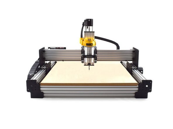
The WorkBee has two methods of supporting the spoiler board. Method 2 has the spoiler board 40mm lower than Method 1.
-
With Method 1, the maximum depth of material that can be cut the whole way through is 27.0mm. If this is adequate for the intended use then stick with Method 1.
-
If greater than 27.0mm cut depth is needed, then choose Method 2, which has 47.0mm of cut depth.
-
Choosing Method 2 will give you 20mm of extra cut depth, however the Z-Axis will have to reach down further to cut thinner materials, so accuracy will be lost. These calculations are based on a 12mm spoiler board.
-
This image references Method 1.
-
-
-
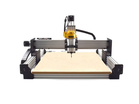
With Method 2 the spoiler board support extrusions are not resting on the workbench, instead they span from front to back
-
There will be two spare extrusions that can be used to support the spoiler board.
-
Machine sizes with an X-Axis of 1000mm or greater have more than two spoiler board supports, therefore there will be 1 or 2 spoiler board support extrusions that you cannot carry out this process.
-
We recommend placing the supported spoiler board supports down the middle, and the unsupported ones along the outer edge of the machine.
-
This image references Method 2.
-


Before you get into the build, we just wanted to thank you for purchasing one of The Ooznest Original WorkBee CNC Machines! We hope you enjoy this journey and we're here to help you every step of the way! Without further ado, let's get started!
Before you get into the build, we just wanted to thank you for purchasing one of The Ooznest Original WorkBee CNC Machines! We hope you enjoy this journey and we're here to help you every step of the way! Without further ado, let's get started!
Cancel: I did not complete this guide.
71 other people completed this guide.
6 Comments
What is the difference between the Version 2.0 and the Version 2.1 instructions?
I am getting the Workbee 500 x 500 and am curious as to which set of instructions I am supposed to use.
John Sigsworth - Resolved on Release Reply
How about offering Method 3:
* not using the “spoiler board support extrusions“ that are in the middle of the bottom (the bracing beams parallel to the Y) at all.
* Bolt the chassi to the table with “Universal L Brackets - Triple“ (that will give stability to the machine without the bracing),
* Puting the spoilboard within the frame and not on the frame , that way you will get even more Z height, sure it would be less accurate but for some jobs at will be enough, and when you want, add a method2 spoilerboard.
What do you all think?
eyaleliyahu@gmail.com - Resolved on Release Reply
For those working with the 1000 - 1500mm machine and have 3 - 2080 - 1460mm supports - and only 2 - of the 2040 - 915mm support but want the full support of method 1 - take your 915mm and space evenly under the Y axis front and rear supports and attach and space the 3 2080 x 1460mm as you would in method 1 - this does make the frame higher from the table but solid support on ends for spoiler board is achieved.
Thanks for the comment, I will certainly work on getting this done, Technical Drawings of both Methods would be better to view for methods 1 & 2 Assemblies!
Ryan Christy - Resolved on Release Reply
It would be nice to see photos of both spoil board methods with and without the board attached.
SnoozeDoggyDog - Resolved on Release Reply