
-
-
If the wires in your kit have white printed tags, please ignore this step. Each wire, at the connector end has a coloured clip with a number. This colour and number identifies this wire. Please see key below.
-
(0)(Black) X-Axis Limit Switch
-
(1)(Brown) Y-Axis Limit Switch
-
(2)(Red) Z-Axis Limit Switch
-
(3)(Orange) X-Axis Stepper Motor Wire.
-
(4)(Yellow) Left Y-Axis Stepper Motor Wire.
-
(5)(Green) Right Y-Axis Stepper Motor Wire.
-
(6)(Light Blue) Z-Axis Stepper Motor Wire.
-
-
-
WorkBee Kits may include different version drag chains, please refer to the correct drawings for assembly of the version supplied.
-
Attach a Drag-Chain-Fixed-End to the Y-Drag-Chain-Fixed-End-Mount in the orientation shown above, using 3 x M5-Low-Profile-15mm bolts and 3 x M5-Nyloc-Nuts.
-
Attach a Drag-Chain-Fixed-End to the Y-Drag-Chain-Fixed-End-Mount in the orientation shown above, using 2 x M5-Low-Profile-15mm bolts and 2 x M5-Nyloc-Nuts.
-
-
-
Position the Y-Axis-Fixed-End-Assembly to the back left corner of the WorkBee.
-
It should be flush with the end of the C-Beam-750mm. Secure it using 2 x M5-Low-Profile-25mm bolts and 2 x M5-Drop-In-Tee-Nuts.
-
-
-
WorkBee Kits may include different version drag chains, please refer to the correct drawings for assembly of the version supplied.
-
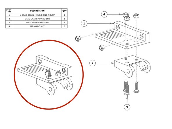
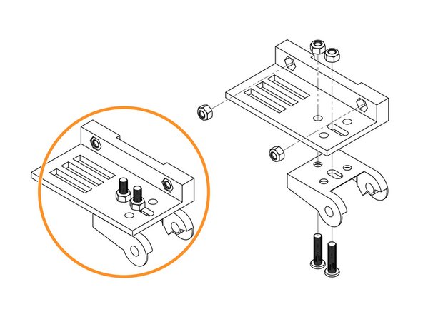
Insert 2 x M5-Nyloc-Nuts into the insets on the Y-Drag-Chain-Moving-End-Mount. They are a snug fit, so may require a light tap with a hammer.
-
Attach a Drag-Chain-Moving-End to the Y-Drag-Chain-Moving-End-Mount in the orientation shown above using 3 x M5-Low-Profile-15mm bolts and 3 x M5-Nyloc-Nuts.
-
Attach a Drag-Chain-Moving-End to the Y-Drag-Chain-Moving-End-Mount in the orientation shown above using 2 x M5-Low-Profile-15mm bolts and 2 x M5-Nyloc-Nuts.
-
-
-
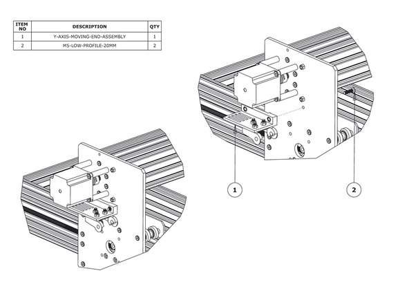
Secure the Y-Axis-Moving-End-Assembly using 2 x M5-Low-Profile-20mm bolts and the 2 x M5-Nyloc-Nuts already inserted into Y-Drag-Chain-Moving-End-Mount.
-
-
-
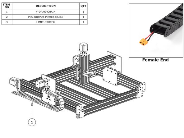
Lay the Y-Drag-Chain flat on a table. Feed the PSU-Output-Power-Cable through the whole length of the Y-Drag-Chain. Ensure that the end with the XT60-Connector, is located at the female end of the Y-Drag-Chain. (as shown in the ‘Female End’ image).
-
Feed the two (4)(Yellow) & (5)(Green) Y-Axis Stepper Motor Wires through the Y Drag-Chain. The end of the stepper motor wires with the black connector should be at the female end of the Y-Drag-Chain - same as above.
-
Feed the wires on the (1)(Brown) Y-Axis Limit-Switch, through the Y Drag-Chain. The switch portion of the Limit-Switch should be at the female end of the Y-Drag-Chain.
-
If you have the Ethernet version of the Duet, now would be a good time to also insert this wire.
-
The tabs of the Drag-Chain can be flipped open with a small flathead screwdriver. Doing this will help to feed the cables.
-
Lay the Y-Drag-Chain flat along the left side of the WorkBee. The female end of the Y-Drag-Chain should be at the back of the machine, and the male end at the front.
-
Attach the female end of the Y-Drag-Chain to the Drag-Chain-Fixed-End on the Y-Axis Fixed-End-Assembly. It will take some force to click it into the Drag-Chain-Fixed-End. A small flathead screwdriver can be used to help pry the Drag-Chain in place.
-
Bring the male end of the Y-Drag-Chain to the Y-Axis-Moving-End-Assembly and attach it to the Drag-Chain-Moving-End. It will take some force to click it into the Drag-Chain-Moving-End. A small flathead screwdriver can be used to help pry the Drag-Chain in place.
-


Thanks for following the guide. Any issues, please contact us!
Thanks for following the guide. Any issues, please contact us!
Cancel: I did not complete this guide.
22 other people completed this guide.

3 Comments
For the longer Y drag chain on the 1500 x1500, I had to remove two of the links as it hit the left hand corner plate before the X arm had reached the end.
Phil Broom - Resolved on Release Reply
Any chance of an update here?
1500 x1500 which drag chain is the left which is at the rear, one is shorter tan the other.
Im sure the sizes for theoter models would help too.
MuddyPotter - Resolved on Release Reply
Hi,
On the cable carrier packaging strap, there should be a barcode, which indicates whether it is X or Y. The Longer one is always the Y-Axis.