
-
-
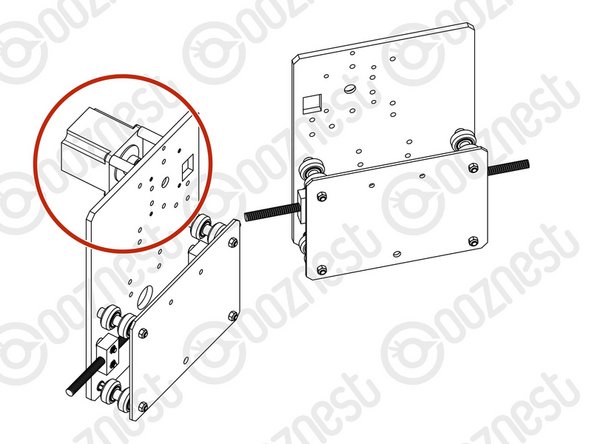
If you have a WorkBee 2.2.1 please follow the Purple Points and look at Image 1. If you have a WorkBee 2.2 please follow the Green Points and look at Image 2.
-
Attach 2 x ACME-Nut-Blocks to one of the Y-Plates using 4 x M5-Low-Profile-25mm bolts & 4 x M5-Nyloc-Nuts. Only loosely tighten these bolts so the ACME-Nut-Blocks can still move side to side.
-
Thread a Y-ACME-Lead-Screw through both ACME-Nut-Blocks. Tighten the bolts holding one of the ACME-Nut-Blocks, making sure it is square to the Y-Plate.
-
To remove any backlash, pinch the loose ACME-Nut-Block towards the previous one, and tighten the bolts holding it. Leave the Y-ACME-Lead-Screw threaded through the ACME-Nut-Blocks.
-
--- WorkBee 2.2 ---
-
Attach 2 x ACME-Nut-Blocks to one of the Y-Plates using 4 x M5-Low-Profile-25mm bolts & 4 x M5-Nyloc-Nuts. On each bolt, in-between the ACME-Nut-Block and Y-Plate, there should be an Aluminium-Spacer-3mm and a Precision-Shim. Only loosely tighten these bolts so the ACME-Nut-Blocks can still move side to side.
-
Thread a Y-ACME-Lead-Screw through both ACME-Nut-Blocks. Tighten the bolts holding one of the ACME-Nut-Blocks, making sure it is square to the Y-Plate.
-
To remove any backlash, pinch the loose ACME-Nut-Block towards the previous one, and tighten the bolts holding it. Leave the Y-ACME-Lead-Screw threaded through the ACME-Nut-Blocks.
-
-
-
First attach the bottom right wheel set; insert a M5-Low-Profile-60mm bolt through the Y-Plate-Assembly from the back. On to this bolt, add an Eccentric-Spacer-6mm, Precision-Shim, Solid-V-Wheel-Xtreme-Assembly, Aluminium Spacer-9mm, Solid-V-Wheel-Xtreme-Assembly, Precision Shim, and a Eccentric-Spacer-6mm in this order.
-
Next, add a Y-Plate-Inner onto the top of this assemblage, add a Precision-Shim and then slightly thread on a M5-Nyloc-Nut. The rounded portion of the Eccentric-Spacer-6mm should be inserted into the hole on either the Y-Plate-Assembly or Y-Plate-Inner (depending on which side it is on).
-
Repeat for the other wheel set on the bottom row corner.
-
Repeat for the 2 wheel sets on the top row, however for these sets use Aluminium-Spacer-6mms instead of Eccentric-Spacer-6mms.
-
Once all of the wheels are attached the M5-Nyloc-Nuts can be tightened down. Ensure that the Solid-V-Xtreme-Wheels can still rotate freely. On the hexagonal portion of the Eccentric-Spacer-6mm, there will be one face that is marked with ‘6mm’.
-
Using a spanner, adjust each Eccentric-Spacer-6mm so that this face is facing downwards. Doing this maximizes the gap between the top and bottom row of wheels.
-
Try to get all the wheels touching the aluminium extrusion as best as possible. It is not a problem, if there is one wheel which is slightly looser than the others. After the machine has been operational for a little while, they will bed in.
-
-
-
Run any piece of C-Beam extrusion in-between the two rows of wheels. Initially, there may be a small amount of play between the C-Beam and wheels. Turn the assembly upside down so the C-Beam is sitting on the row of wheels with the Aluminium-Spacer-6mms.
-
Starting with one pair of wheels, adjust both Eccentric-Spacer-6mms down onto the C-Beam Extrusion until there is a small amount of friction between both wheels and the C-Beam Extrusion.
-
When adjusting the pair of Eccentric-Spacer-6mms ideally they should be adjusted identically. However, sometimes one will need to be adjusted slightly more than the other to get both wheels engaged with the C-Beam extrusion.
-
Repeat for the other pair of wheels with eccentric spacers.
-
Slide the C-Beam extrusion back and forth through the wheels. This should require a small amount of force, and all wheels should spin as it rolls. Also check there is no wobbling of the extrusion. Once happy, double check the tightness of the M5-Nyloc Nuts.
-
-
-
Repeat the this section for other Y-Plate. As seen it should be a mirror image of the previous assembly.
-
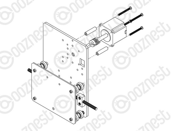
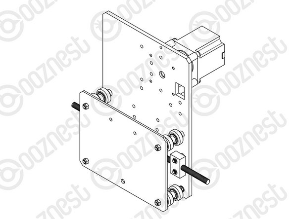
A NEMA23-Stepper-Motor needs to be attached to the second Y-Plate Assembly. See pictures 2 & 3.
-
Slide the 1/4” side (the side with the smallest hole) of the Flexible-Coupler onto the shaft of the NEMA23-Stepper-Motor. Don’t tighten it down at this point.
-
Attach the NEMA23-Stepper-Motor to the threaded holes on the Y-Plate using 4 x M5-Low-Profile-50mm bolts and 4 x Aluminium-Spacer-40mm’s.
-
Orient the NEMA23-Stepper-Motor so that the wire is towards the back of the Y-Plate (the side closet to the small rectangle opening).
-
The Y-Plate Assembly with the NEMA23-Stepper-Motor will be known going forward as the Y-Plate-Left Assembly.
-
The other Y-Plate Assembly (Without the NEMA23-Stepper-Motor) will be known going forward as the Y-Plate-Right Assembly.
-


Thanks for following the guide. Any issues, please contact us!
Thanks for following the guide. Any issues, please contact us!
Cancel: I did not complete this guide.
34 other people completed this guide.
