
-
-
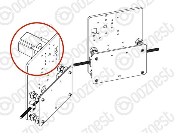
If you have a WorkBee 2.2.1 please follow the Purple Points and look at Image 1. If you have a WorkBee 2.2 please follow the Green Points and look at Image 2.
-
Attach 2 x ACME-Nut-Blocks to one of the Y-Plates using 4 x M5-Low-Profile-25mm bolts & 4 x M5-Nyloc-Nuts. Only loosely tighten these bolts so the ACME-Nut-Blocks can still move side to side.
-
Thread a Y-ACME-Lead-Screw through both ACME-Nut-Blocks. Tighten the bolts holding one of the ACME-Nut-Blocks, making sure it is square to the Y-Plate.
-
To remove any backlash, pinch the loose ACME-Nut-Block towards the previous one, and tighten the bolts holding it. Leave the Y-ACME-Lead-Screw threaded through the ACME-Nut-Blocks.
-
--- WorkBee 2.2 ---
-
Attach 2 x ACME-Nut-Blocks to one of the Y-Plates using 4 x M5-Low-Profile-25mm bolts & 4 x M5-Nyloc-Nuts. On each bolt, in-between the ACME-Nut-Block and Y-Plate, there should be an Aluminium-Spacer-3mm and a Precision-Shim. Only loosely tighten these bolts so the ACME-Nut-Blocks can still move side to side.
-
Thread a Y-ACME-Lead-Screw through both ACME-Nut-Blocks. Tighten the bolts holding one of the ACME-Nut-Blocks, making sure it is square to the Y-Plate.
-
To remove any backlash, pinch the loose ACME-Nut-Block towards the previous one, and tighten the bolts holding it. Leave the Y-ACME-Lead-Screw threaded through the ACME-Nut-Blocks.
-
-
-
First attach the bottom right wheel set; insert a M5-Low-Profile-60mm bolt through the Y-Plate-Assembly from the back. On to this bolt, add an Eccentric-Spacer-6mm, Precision-Shim, Solid-V-Wheel-Xtreme-Assembly, Aluminium Spacer-9mm, Solid-V-Wheel-Xtreme-Assembly, Precision Shim, and a Eccentric-Spacer-6mm in this order.
-
Next, add a Y-Plate-Inner onto the top of this assemblage, add a Precision-Shim and then slightly thread on a M5-Nyloc-Nut. The rounded portion of the Eccentric-Spacer-6mm should be inserted into the hole on either the Y-Plate-Assembly or Y-Plate-Inner (depending on which side it is on).
-
Repeat for the other wheel set on the bottom row corner.
-
Repeat for the 2 wheel sets on the top row, however for these sets use Aluminium-Spacer-6mms instead of Eccentric-Spacer-6mms.
-
Once all of the wheels are attached the M5-Nyloc-Nuts can be tightened down. Ensure that the Solid-V-Xtreme-Wheels can still rotate freely. On the hexagonal portion of the Eccentric-Spacer-6mm, there will be one face that is marked with ‘6mm’.
-
Using a spanner, adjust each Eccentric-Spacer-6mm so that this face is facing downwards. Doing this maximizes the gap between the top and bottom row of wheels.
-
Try to get all the wheels touching the aluminium extrusion as best as possible. It is not a problem, if there is one wheel which is slightly looser than the others. After the machine has been operational for a little while, they will bed in.
the top 2 holes on the Y plate inner and the corresponding holes on the Y Plate are smaller than the bottom holes which means the eccentric spacer doesn’t sit in the hole making the bolt to short and the y plate sits at an angle. should i drill these holes out to match the bottom ones??
Andrew Mooney - Resolved on Release Reply
Correct the top holes use the 6mm Spacers as refereed to by @mattf, I have now highlighted this in the guide.
Nope, the top holes use a normal 6mm spacer rather than eccentric one. It does say in the doc although its not highlighted - just did this bit myself and had to re-read it a couple of times.
Matt F -
-
-
-
Run any piece of C-Beam extrusion in-between the two rows of wheels. Initially, there may be a small amount of play between the C-Beam and wheels. Turn the assembly upside down so the C-Beam is sitting on the row of wheels with the Aluminium-Spacer-6mms.
-
Starting with one pair of wheels, adjust both Eccentric-Spacer-6mms down onto the C-Beam Extrusion until there is a small amount of friction between both wheels and the C-Beam Extrusion.
-
When adjusting the pair of Eccentric-Spacer-6mms ideally they should be adjusted identically. However, sometimes one will need to be adjusted slightly more than the other to get both wheels engaged with the C-Beam extrusion.
-
Repeat for the other pair of wheels with eccentric spacers.
-
Slide the C-Beam extrusion back and forth through the wheels. This should require a small amount of force, and all wheels should spin as it rolls. Also check there is no wobbling of the extrusion. Once happy, double check the tightness of the M5-Nyloc Nuts.
-
-
-
Repeat the this section for other Y-Plate. As seen it should be a mirror image of the previous assembly.
-
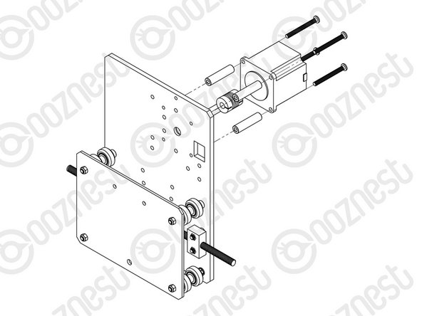
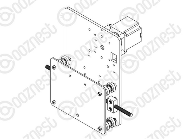
A NEMA23-Stepper-Motor needs to be attached to the second Y-Plate Assembly. See pictures 2 & 3.
-
Slide the 1/4” side (the side with the smallest hole) of the Flexible-Coupler onto the shaft of the NEMA23-Stepper-Motor. Don’t tighten it down at this point.
-
Attach the NEMA23-Stepper-Motor to the threaded holes on the Y-Plate using 4 x M5-Low-Profile-50mm bolts and 4 x Aluminium-Spacer-40mm’s.
-
Orient the NEMA23-Stepper-Motor so that the wire is towards the back of the Y-Plate (the side closet to the small rectangle opening).
-
The Y-Plate Assembly with the NEMA23-Stepper-Motor will be known going forward as the Y-Plate-Left Assembly.
-
The other Y-Plate Assembly (Without the NEMA23-Stepper-Motor) will be known going forward as the Y-Plate-Right Assembly.
Hi Chris,
Thanks for your comment, Great you found an easier way which worked for you, the reason we do it this way is so that a lot of components are already mounted to the plates and easier to access once assembled.
Ryan Christy - Resolved on Release Reply
I actually found it was easier not to install the X Stepper Motor until 4. X-Gantry Assembly Step 3. when you are fitting the bearings and flexi-coupler to the X-ACME Screw. This allows you to offer up the Step Motor without a coupler and get the 1mm gap correct before slotting everything together. The plates also store better for a few steps without a heavy step motor on one!
Also its worth popping a pen-mark on the stepper motor shaft to show where the flat portion is as this cannot be seen once the flexi coupler is attached. Again this will help with the final line up.
Chris Davies - Resolved on Release Reply
-


Thanks for following the guide. Any issues, please contact us!
Thanks for following the guide. Any issues, please contact us!
Cancel: I did not complete this guide.
34 other people completed this guide.

If the lead screw becomes tight AFTER all the bolts are tight then it could be that one or both of the nut blocks are not flat against the back plate, they need to be square to the bottom edge and the block must sit flat on the back plate. Loosen one of the blocks. Work the lead screw (now free again we hope) so that the block can find a natural position flat and square. Then tighten the bolts. Test again. If stuck try again. Make sure both blocks are flat.
Mike - Resolved on Release Reply
Hi Prenny,
Thanks for your email. It should matter too much, it will loosen up after you start using the machine.
Best Regards
Ryan Lock
Ryan Lock - Resolved on Release Reply
Does it matter if the lead screw is threading tightly or loosely once both nut-blocks are tightened? Would it affect the longevity of the stepper?
Prenny Abraham - Resolved on Release Reply