
Introduction
Please read before proceeding to avoid damaging the controller and voiding your warranty
- Avoid connecting the Duet via USB when you do not need to. (Except when instructed to in the guides)
- Always unplug the WorkBee Power Supply before connecting the USB Cable.
-
-
If looking at the machine from the front the correct axis motion is, X-Axis is positive towards the right.
-
The Y-Axis is positive going away.
-
The Z-Axis is positive going up.
-
-
-
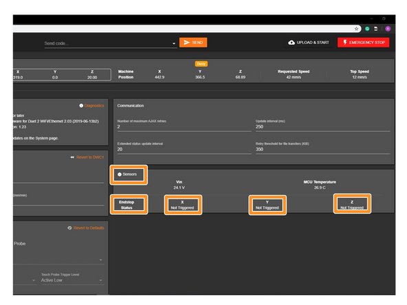
In WorkBee Control, under Settings > Machine-Specific > Sensors, take note of the Vin number. It needs to read 24.0V. If it does not read 24.0V, please follow the steps below.
-
Using an insulated Phillips Screw Driver adjust the Power Supply output voltage by rotating the white plastic screw inside the Ooznest Logo.
-
Adjust the output voltage so it reads 24.0
-
-
-
In WorkBee Web Control under to Settings > Machine Specific > Sensors, you will find the statuses of the limit switches.
-
Activate the X-Axis limit switch with your finger. Hold for a few seconds.
-
The endstop status should change to 'Triggered'
-
It is normal for there to be a delay between pressing the limit switch and the status being updated. Please do not be concerned, the board will stop the motor instantaneously.
-
Repeat this procedure for the Y & Z Limit switches.
-
If any do not behave as intended do not proceed with this guide, please contact us: https://ooznest.co.uk/help/
-
-
-
If any of the limit switches did not behave as intended in the previous step, do not proceed with this step & guide, please contact us: https://ooznest.co.uk/help/
-
When the machine homes, it will raise the Z-Axis, and then move the X and Y-Axis to the far right-hand corner.
-
If any of the points below do not behave as explained, do not proceed with this guide, please contact us: https://ooznest.co.uk/help/
-
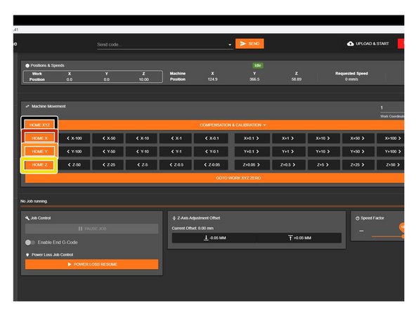
Press Home Z. The Z-Axis should raise upwards, bounce once on the limit switch, and then stop.
-
Press Home X. The Z-Axis should home like the previous. The X-Axis should then move towards the right, bounce once on the limit switch, and then stop.
-
Press Home Y. The Z-Axis should home like previous. The Y-Axis should then move towards the back, bounce once on the limit switch, and then stop.
-
Press Home All. The Z-Axis should home like previous. Then the X and Y-Axis should home like previous.
-
-
-
Re-home the machine so the machine is at the maximum on all axes.
-
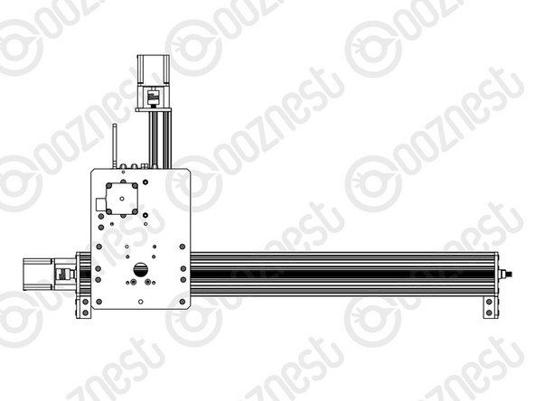
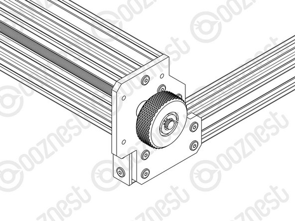
On the Left Hand Y-Axis ACME Screw , if looking from the front, thread the Tensioning-Knob onto the end of the ACME Screw.
-
Loosen the 8mm-Clamping-Collar.
-
Turn the Tensioning-Knob clockwise, you will feel the screw tension, turn it until the motor clicks over.
-
Just before this point where the motor clicks, is the correct tension for the ACME Screw. While holding the tensioning knob at this point, push the 8mm-Clamping-Collar against the 8mm-Shim and F688ZZ-Bearing and tighten the 8mm-Clamping-Collar.
-
Remove the Tensioning-Knob.
-
Repeat for the Right Hand Y-Axis Screw.
-
To tension the X-Axis screw jog the machine furthest left and repeat the above steps to tension correctly.
-
-
-
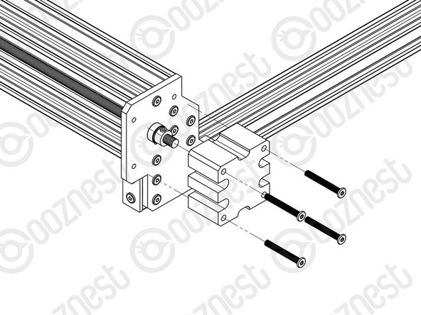
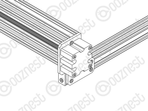
Onto the end of each ACME Screw attach an ACME-End-Cap using 4 x M5-Low-Profile-40mm bolts.
-
-
-
Congratulations you have completed the assembly and testing of your Ooznest Original WorkBee CNC Machine.
-
We recommend following these two guides to learn how to use your WorkBee: WorkBee Control Overview & How To Set up a Job on the WorkBee CNC Machine
-


Thanks for following the guide. Testing of the WorkBee is now complete!
Thanks for following the guide. Testing of the WorkBee is now complete!
Cancel: I did not complete this guide.
17 other people completed this guide.
