
Introduction
This guide will talk you through step by step how to run your first project on the Ooznest Original WorkBee CNC Machine using the WorkBee Control Interface, We have written this guide making reference to the two most popular software packages used on the WorkBee CNC Machine, these are Vectric's Cut2D/V-Carve/Aspire and Autodesk's Fusion 360.
-
-
Clamp your selected material to the Spoilerboard of your WorkBee CNC Machine and hold in place using your chosen method this could be any of the following: Screws, Clamps with Tee Nut Waste Board or T-Track.
-
In this guide we are using a piece of 140x140x18mm MDF Board
-
Once your material is clamped in place and is parallel with the movement of your machine secure your chosen Endmill in the collet tightly.
-
-
-
Switch your Machine on by the mains and Connect to the Machine using the IP Address setup in the assembly guides: Assembling Your WorkBee - V2.3 - V2.3.1
-
Home the XYZ Axis by clicking the relevant function. With the Machine homed jog the Machine to your XYZ Datum Position you set in your CAM Program, we prefer to use the Surface of the material for our Z Datum and the Front Left Corner for the X & Y.
-
To make finding this corner easier you could use the Ooznest XYZ Touch Probe
-
With the Machine in position, set the Work XYZ Zero using the function, Note that the Work Position now reads 0, 0, 0.
-
If you jog the machine away from this corner and press Goto to XYZ Zero, you should note your machine goes to the exact point set above.
-
-
-
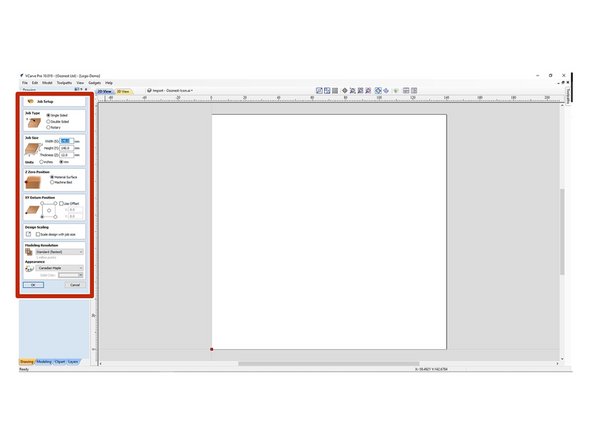
In the CAM Program configure your Job Setup, adding in the relevant information for the Job Type, Size and Z Datum and XY Zero Position.
-
This should always be set for the exact same position as Work Zero Position physically set on your machine. In this case, the surface of the material for our Z Datum and front left corner for the X & Y Zero position.
-
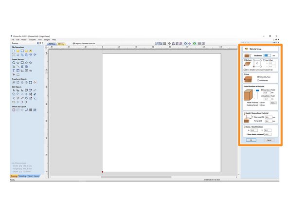
On the Material Setup Section check the settings match your Job Setup and alter the Rapid & Home/Start Position Z Gap above material to accommodate any surface clamps you may have generally we set this value to 5mm.
-
If when running your job on the machine you get an 'Outside Machine Limits' Error, the reason is normally because these values are set too high.
-
-
-
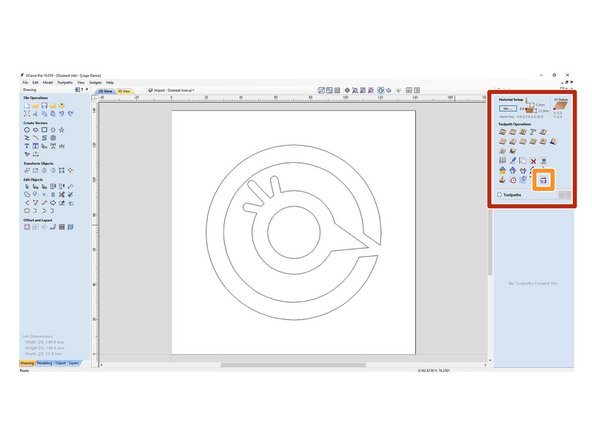
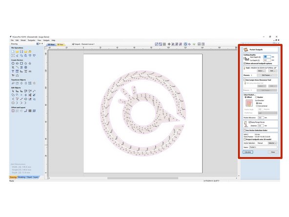
Once you have your design in place choose the relevant Tool Operation defining your Cutting Depths, Tool and any Pocket or Profile allowances required for your Project and Calculate the Toolpath.
-
This design used in this guide can be downloaded Here. It can be imported under File > Import > Import Vectors
-
In the Preview Toolpaths section, view the Toolpath to ensure the Job is correct. Using the Save Toolpath Function Select Grbl (mm) (*.gcode) or Duet Arcs (mm) (*.gcode) Post Processors. Save the G-Code file on your computer in a location you will be able to find later.
-
To learn more about using Vectric software we recommend watching Vectric's channel here
-
-
-
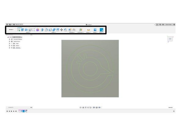
In the Design workspace in Fusion use the tools to create your project, sketch your project on the workspace and extrude your objects to create a 3D Model.
-
This design used in this guide can be downloaded Here. It can be imported using File > Open
-
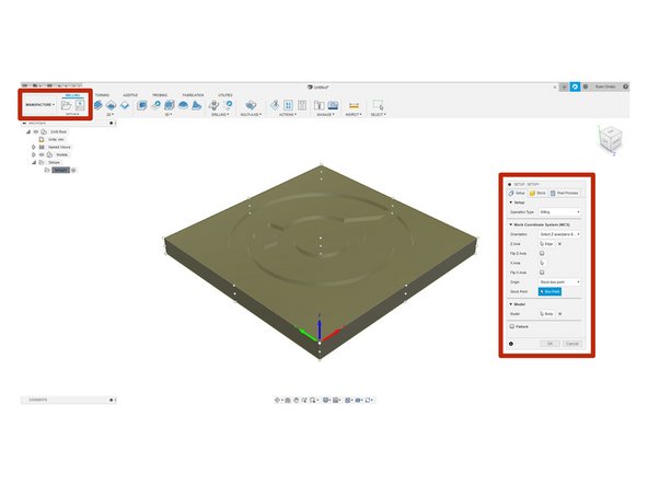
In the Manufacture workspace configure your Job Setup, Under Setup define the Operation type as Milling.
-
Next under Work Coordinate System define the Orientation of each axis and set your Origin Point.
-
This should always be set for the exact same position as Work Zero Position physically set on your machine. In this case, the surface of the material for our Z Datum and front left corner for the X & Y Zero position.
-
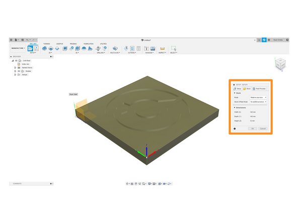
Under the Stock Tab, set Stock Mode to 'Relative Size Box'
-
-
-
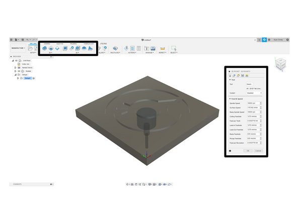
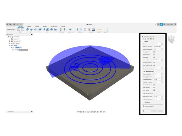
Once the appropriate Toolpath has been selected define the Tool and the relevant Feed & Speed rates for your project selecting the Geometry or model from the workspace.
-
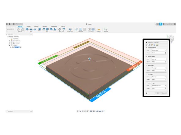
Define the Heights and Passes suited to your project, and click ok take into account any surface clamps you may have and the pass depth suitable to your Endmill
-
If when running your job on the machine you get an 'Outside Machine Limits' Error, the reason is normally because the Heights are set too high.
-
-
-
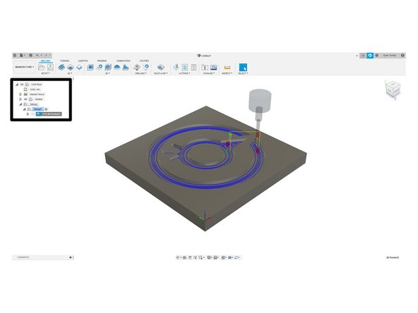
Once you have set up the appropriate toolpath for your project it will appear on the left column and you will be able to visually see the toolpath highlighted.
-
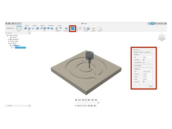
Preview the Toolpath using the Simulate Function, using the same settings as we have here will allow you to view the cut.
-
Install the WorkBee Post Processor following the guide which can be found here
-
Click Post Process in the toolbar and save the G-Code file on your computer in a location you will be able to find later. Use the WorkBee Post Processor which was installed earlier.
-
To learn more about using Fusion360 we recommend watching Lars Christensen's channel here
-
-
-
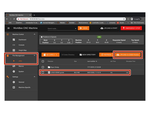
Under File Management ->Jobs click Upload G Code File(s) and locate the G-Code saved previously on your computer.
-
Once uploaded the job is now stored on the Duets onboard SD Card and can be used multiple times, to delete a project file right click and delete.
-
-
-
Turn on your Dust Extraction if needed.
-
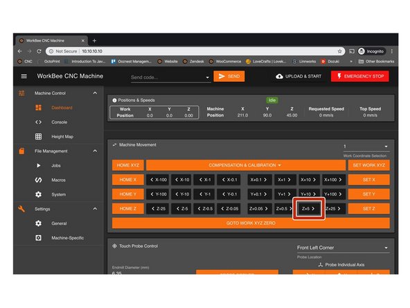
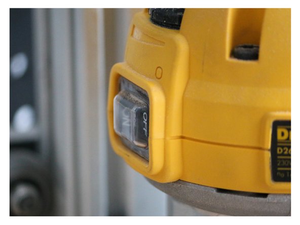
Jog the Machine up by 5mm using the +Z Button. Turn on your router, Adjust the RPM on your router to match what you have setup in your CAM program.
-
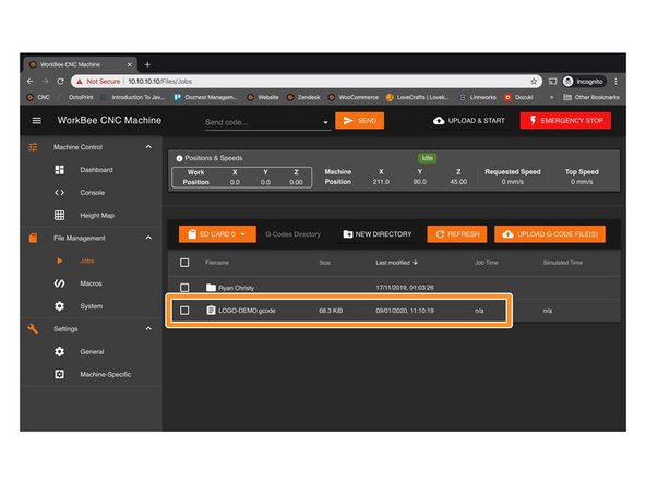
Under Jobs select the project you wish to start and click run. During the Job, you will be able to pause the program to make any adjustments or cancel using the functions in the Control Interface.
-
For a more in-depth guide on using WorkBee Control please follow this guide: WorkBee Control Overview
-
-
-
Once the job has finished we advise that you switch off the router once the machine has returned to your work zero position.
-
Now is a good time to home the machine to view your finished project created on your Ooznest Original WorkBee CNC Machine
-


Thanks for following the guide. Any issues, please contact us!
Thanks for following the guide. Any issues, please contact us!

2 Comments
Hi,
Why am I not able to follow this link: 3. Connecting and Commissioning - V2.0 ? I am not authorized to view this page, why not ?
I need to start all over again, please let me view this page.
Mark Wiersma
Mark Wiersma - Resolved on Release Reply