
-
-
Attach the V-Slot-2040-750mm to the back two holes on the Y-Plate-Right-Assembly using 2 x M5-Low-Profile-15mm bolts.
-
Attach the C-Beam-750mm to the four non-threaded holes on the Y-Plate-Right Assembly shown above using 4 x M5-Low-Profile-15mm bolts.
-
-
-
Before the Y-Plate-Left-Assembly can be attached, Tee-Nuts need to be inserted.
-
The Tee-Nuts should be inserted so that the flat face is facing outwards.
-
Insert 2 x Tee-Nuts in to the front facing top slot, 2 x Tee-Nuts in to the front facing bottom slot.
-
Slide the X-Carriage-Assembly onto the C-Beam-750mm in the orientation seen above.
-
Repeat Step 1 for the Y-Plate-Left-Assembly.
-
Recheck the bottom Eccentric-Spacer-6mms on the X-Carriage-Assembly to make sure they are touching the rail, there is no wobble, and that the X-Carriage-Assembly runs smoothly along the whole length of the C-Beam-750mm.
-
Place the X-Gantry Assembly onto a flat table. Check both Y-Plates are sitting flush with the table. Loosen the extrusions and adjust if needed.
-
-
-
Looking at the Y-Plate-Left, adjust the X-ACME-Screw so the end is on the extrusion side of the Y-Plate-Left.
-
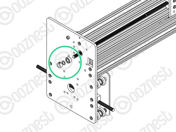
In the gap between the Y-Plate-Left and Flexible-Coupler, insert a 688zz-Bearing, 8mm-Shim, and 8mm-Clamping-Collar. With the 688zz-Bearing closest to the Y-Plate-Left, seated inside the recess.
-
Adjust the X-ACME-Screw back through the 688zz-Bearing, 8mm-Shim, and 8mm-Clamping-Collar, until it touches the NEMA 23-Stepper-Motor shaft.
-
While pushing the 8mm-Clamping-Collar against the 8mm-Shim and 688zz-Bearing into the recess on the Y-Plate-Left, tighten the clamping bolt on the 8mm-Clamping-Collar.
-
Tighten the grub screws on the Flexible-Coupler. Make sure one is on the flat portion of the motor shaft.
-
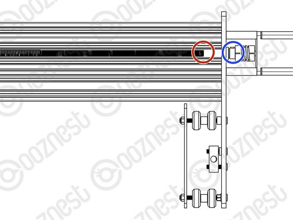
On the outside of the Y-Plate-Right slide on a 688zz-Bearing, 8mm-Shim, and 8mm-Clamping-Collar. Inset the 688zz-Bearing into the recess.
-
While pushing the 8mm-Clamping-Collar against the 8mm-Shim and 688zz-Bearing into the recess on the Y-Plate-Right, tighten the clamping bolt on the 8mm-Clamping-Collar.
-
-
-
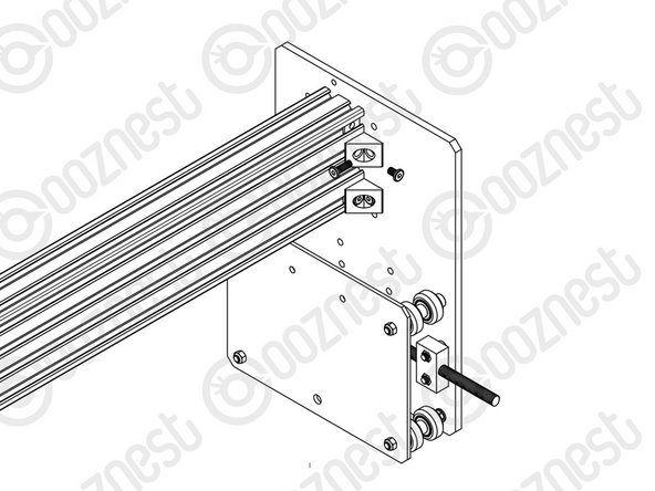
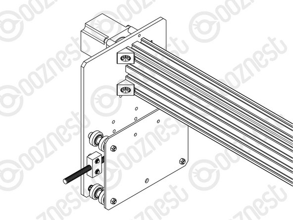
Attach an Angle-Corner to the Y-Plate-Right-Assembly & the front facing top slot of the C-Beam-750mm. A M5-Low-Profile-8mm screws into the Tee-Nut previously inserted, and a M5-Low-Profile-15mm goes though the Angle-Corner and attaches to a M5-Nyloc-Nut on the outside of the Y-Plate-Right-Assembly.
-
Repeat this for the other 3 Angle-Corners in the positions shown above.
-


Thanks for following the guide. Any issues, please contact us!
Thanks for following the guide. Any issues, please contact us!
Cancel: I did not complete this guide.
40 other people completed this guide.

4 Comments
Would be good if the rails and extrusions were pre-threaded for the screws. At the moment they are putting up a fight trying to make the thread.
Hello,
Your extrusions from us should all be pre-tapped to an M5 thread. If you do not have the relevant holes tapped please email some pictures across to sales@ooznest.co.uk and we can arrange to rectify the issue!
Ryan Christy
missing 3x M5 low profile 8mm
Thats the 3rd missing from this kit.. so disappointed after spending all this money. wont be writing a good review at all!!!
jimi barker - Resolved on Release Reply
Where is the best place to route the cable from the limit switch? I managed to get mine stapped by one of the wheels and damaged the insulation.
Brian Trowbridge - Resolved on Release Reply
6 bolts shown, but only 5 dotted lines through the plate… or is one directly underneath another dotted line? Thanks
Andre Ravary - Resolved on Release Reply