
-
-
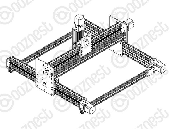
Slide a C-Beam-750mm through each set of wheels on the X-Gantry-Assembly. The Y-ACME-Screws go inside the ‘C’ Channel.
-
Rest the ends of the C-Beam-750mm on 2 x V-Slot-2040-745mm’s. The ends of the extrusions should be flush with the sides of each other.
-
-
-
If possible while carrying out the below steps get a second person to hold the machine square.
-
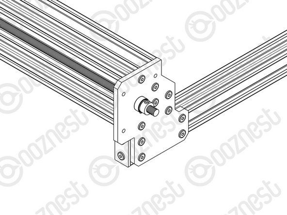
Slide the X-Gantry-Assembly to the front, and attach a Y-End-Plate to the front left corner, first using 4 x M5-Low-Profile-15mms, which screw into the tapped holes on the C-Beam-750mm.
-
Insert 2 x Tee-Nuts into the front facing top and bottom slots of the V-Slot-2040- 745mm. Adjust the Tee-Nuts so they line up with the holes on the Y-End-Plate.
-
Secure the Y-End-Plate to the V-Slot-2040-745mm using 4 x M5-Low-Profile- 12mms. Ensure the end of the V-Slot-2040-745mm is flush with the side of the C Beam-750mm.
-
Square the base, and repeat for the Y-End-Plate on the opposite end of the front V-Slot-2040-745mm.
-
Slide the X-Gantry-Assembly to the back. Square the base, and repeat all the above for the back V-Slot-2040-745mm.
-
-
-
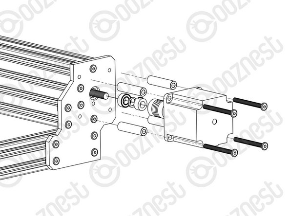
Adjust the left Y-ACME-Screw (as if looking from the front) so roughly 10mm is protruding from the Y-End-Plate at the back of the machine. Slide onto the end a F688zz-Bearing, 8mm-Shim and 8mm-Clamping-Collar, and inset the F688zz-Bearing into the hole on the Y-End-Plate.
-
Slide the 1/4” side (the side with the smallest hole) of the Flexible-Coupler onto the shaft of the NEMA23-Stepper-Motor. Don’t tighten it down at this point.
-
Attach the NEMA23-Stepper-Motor to the threaded holes on the Y-End-Plate using 4 x M5-Low-Profile-50mm bolts and 4 x Aluminium-Spacer-40mms. Adjust the Y-ACME-Screw until there is gap of ~1.0mm (The thickness of a Precision-Shim) between it and the shaft of the NEMA23-Stepper-Motor shaft.
-
Orient the NEMA23-Stepper-Motor so the wire is facing downwards.
-
While pushing the 8mm-Clamping-Collar against the 8mm-Shim and F688zz-Bearing into the recess on the Y-End-Plate, tighten the clamping bolt on the 8mm-Clamping-Collar.
-
Push the Flexible-Coupler up against the 8mm-Clamping-Collar. Tighten the clamping bolt first around the Y-ACME-Screw, then the grub screw onto the Y-ACME-Screw.
-
Rotate the Flexible-Coupler a couple of times to insure it is in a un-stressed state. Then rotate it so the grub screw on the stepper motor side is aligned with the flat portion of the motor shaft. Tighten the clamping bolt first around the motor shaft, then the grub screw onto the flat portion of the motor shaft.
-
Repeat for the final NEMA23-Stepper-Motor attaching it to the Y-End Plate-Left on the back right of the machine.
-
-
-
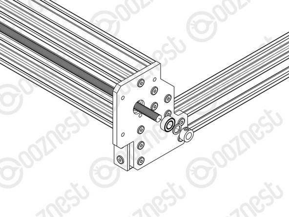
At the front of the machine, onto the two Y-ACME-Screws protruding from the Y-End-Plates slide on a F688zz-Bearing, 8mm-shim, and a 8mm-Clamping-Collar.
-
While pushing the 8mm-Clamping-Collar against the 8mm-Shim and F688zz-Bearing into the hole on the Y-Plate-End-Plates, tighten the clamping bolt on the 8mm-Clamping-Collar.
-


Thanks for following the guide. Any issues, please contact us!
Thanks for following the guide. Any issues, please contact us!
Cancel: I did not complete this guide.
27 other people completed this guide.

2 Comments
Instruction is missing how to use Tensioning-Knob and how install plastic caps to protect Y-ACME-Screw in other end than motor.
Jani Heiskari - Resolved on Release Reply