
Introduction
Please read before proceeding to avoid damaging the controller and voiding your warranty
Do not have the USB cable connected at the same time as the Mains Power.
Do not connect the WorkBee to a computer via USB when you don't need to. The Duet has either an Ethernet or WiFi connection, so USB is generally used only when debugging and initially commissioning the controller. All CNC Operations including uploading G-Code files can be done via the web interface.
Do not connect the Duet via USB to a laptop running off mains power.
Other devices powered from the mains may create ground transients. These will flow through the USB cable and may cause the Duet to reset or perform abnormally.
At no point should you press the reset button on your Controller as this can potentially erase the firmware and require your controller to be sent back for testing.
-
-
If looking at the machine from the front the correct axis motion is, X-Axis is positive towards the right.
-
The Y-Axis is positive going away.
-
The Z-Axis is positive going up.
-
-
-
Remove the USB Cable - If you have the Duet Ethernet leave the Ethernet Cable Plugged in from this point on.
-
Plug in and switch on Mains Power providing you have completed Power Supply Assembly The USB should not be connected at this point! Make sure the switch on the side of the Power Supply is turned on.
-
Open the WorkBee Control and take note of the Vin number that is displayed under Settings - Machine-Specific - Sensors if above or below 24.0 V adjustment must be made.
-
Gently using an insulated Phillips Screw Driver adjust the PSU Voltage gently by locating the White Plastic Screw inside the Ooznest Logo.
-
Once adjustment has been made the Duet Web Control will display the correct Voltage.
-
-
-
To test the machine we need to check each axis moves correctly. For safety reasons, the firmware is setup so the machine cannot be jogged before it is homed. We need to disable this to test the machine.
-
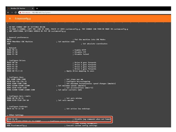
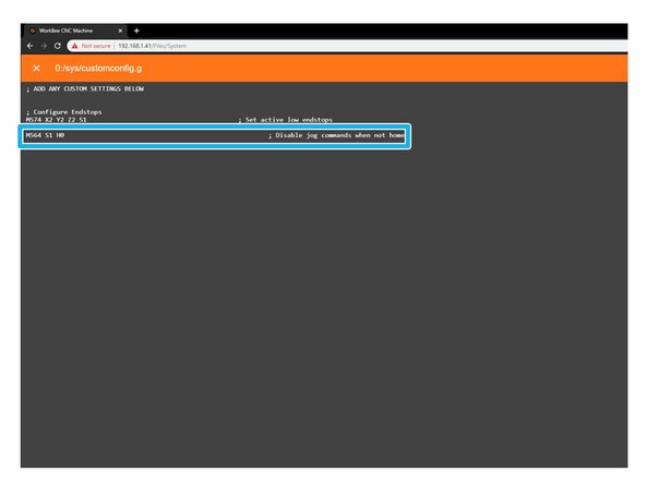
Under File Management open System - Config.g and Copy the Disable Jog Commands information.
-
At the bottom find the line M564 S1 H1
-
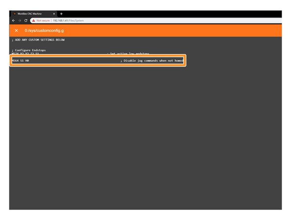
Return back to system and open Customconfig.g and paste in the Disable Jog Commands Lines changing the M564 S1 H1 and alter to M564 S1 H0.
-
Click Save to enable the Changes and Restart using the Emergency Stop Button displayed in the Workbee Control Interface.
-
-
-
Please be very careful when carry out the following steps. Check there is enough travel for the machine to carry out these steps. If there isn't enough travel either reduce the jog amount, or move in the other direction.
-
With the machine roughly in the middle of travel on all its axis. Connect to your WorkBee in WorkBee Control.
-
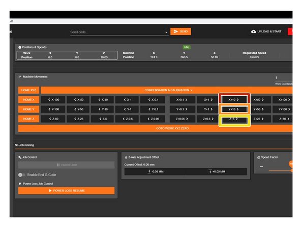
Jog the machine 10mm in the positive X Direction by Press 'X+10'. The machine should move 10mm to the right.
-
Jog the machine 10mm in the positive Y Direction by Press 'Y+10'. The machine should move 10mm to the away from the front.
-
Jog the machine 5mm in the positive Z Direction by Press 'Z+5'. The machine should move 5mm upwards.
-
If any of the axis are travelling in the incorrect direction please refer to this guide to rectify it: How To Change Axis Travel Direction
-
-
-
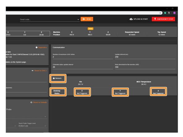
In WorkBee Web Control Navigate to Settings > Machine Specific. Activate the X-Axis limit switch with your finger. Hold for a few seconds. The endstop status should change to 'Triggered'
-
It is normal for there to be a delay between pressing the limit switch and the status being updated. Please do not be concerned, the board itself will stop the motor instantaneously after it has been switched. You can test this, as there is a red light on the board which will show when the limit switch is pressed.
-
Repeat this procedure for the Y & Z Limit switches.
-
If your limit switches are showing as 'Triggered' when they are not physically pressed, but change to 'Not Triggered' when physically pressed, please complete this guide: How To Invert Limit Switches
-
If any do not behave as intended, please check they are wired into the correct inputs.
-
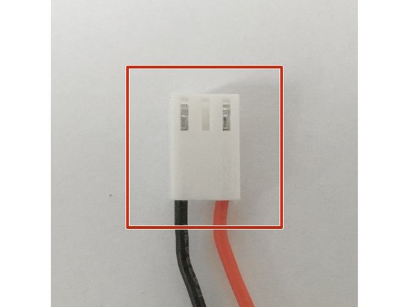
If they are wired correctly. Please check they have been manufactured correctly. The wiring on the connector side should match image 2.
-
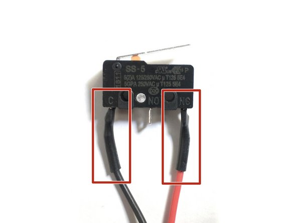
The wiring on the limit switch side should match image 3.
-
Please contact us if they have been manufactured incorrectly and we will send out a replacement unit.
-
-
-
Only attempt this step if you have successfully completed the previous step.
-
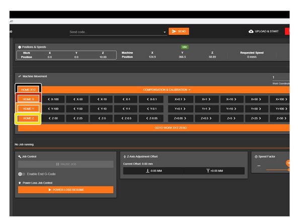
When the machine homes it should raise the Z-Axis and stop, and then Home the X and Y-Axis to the far right hand corner.
-
Press Home Z. The Z-Axis should raise upwards, bounce once on the limit switch, and then stop.
-
Press Home X. The Z-Axis should home like the previous step. The X-Axis should then move towards the right, bounce once on the limit switch, and then stop.
-
Press Home Y. The Z-Axis should home like previous. The Y-Axis should then move towards the back, bounce once on the limit switch, and then stop.
-
Press Home All. The Z-Axis should home like previous. Then the X and Y-Axis should home like previous.
-
Once testing is complete, repeat Step 3 but remove the Disable Jog lines from Customconfig.g
-
-
-
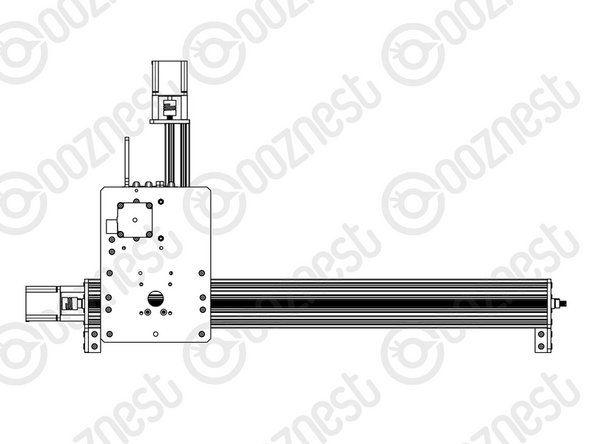
Re-home the machine so the machine is at the maximum on all axes.
-
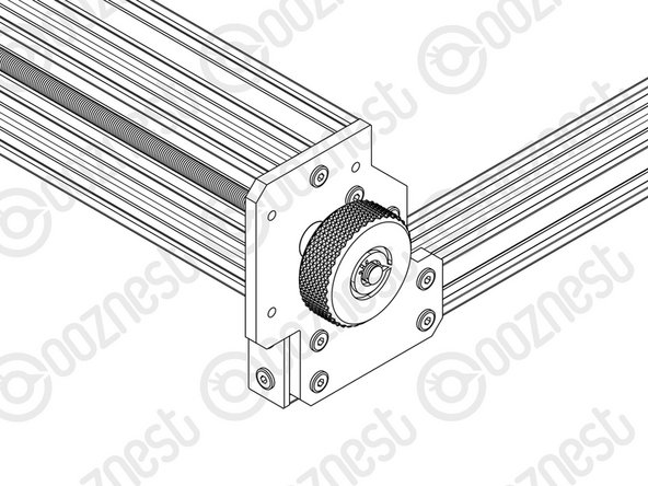
On the Left Hand Y-Axis ACME Screw , if looking from the front, thread the Tensioning-Knob onto the end of the ACME Screw.
-
Loosen the 8mm-Clamping-Collar.
-
Turn the Tensioning-Knob clockwise, you will feel the screw tension, turn it until the motor clicks over.
-
Just before this point where the motor clicks, is the correct tension for the ACME Screw. While holding the tensioning knob at this point, push the 8mm-Clamping-Collar against the 8mm-Shim and F688ZZ-Bearing and tighten the 8mm-Clamping-Collar.
-
Remove the Tensioning-Knob.
-
Repeat for the Right Hand Y-Axis Screw and the X-Axis screw.
-
-
-
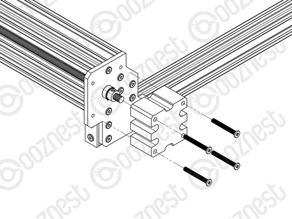
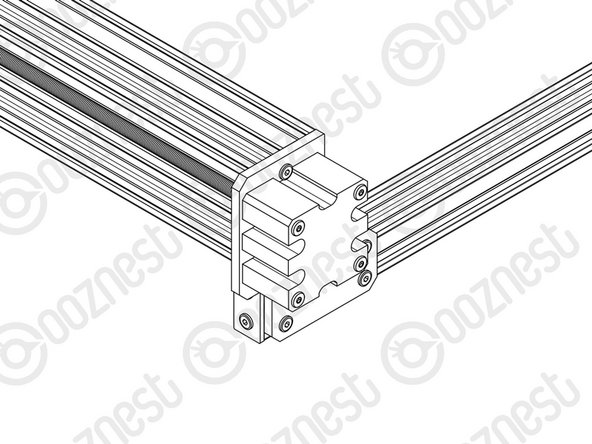
Onto the end of each ACME Screw attach an ACME-End-Cap using 4 x M5-Low-Profile-40mm bolts.
-
-
-
Congratulations you have completed the assembly and testing of your Ooznest Original WorkBee CNC Machine.
-
We recommend following these two guides to learn how to use your WorkBee: WorkBee Control Overview & How To Set up a Job on the WorkBee CNC Machine
-


Thanks for following the guide. Testing of the WorkBee is now complete!
Thanks for following the guide. Testing of the WorkBee is now complete!
Cancel: I did not complete this guide.
8 other people completed this guide.

2 Comments
Wow! Got here! All working as expected, just making sure all the details are correct but essentially it looks at it should do. I still have a lot of nuts bolts and bits left over - I was concerned I missed something but that seems to be a bit thoughtful excess to assist the builder. The part that gave the most trouble was configuring the Duet board , I have some sympathy for Ooznest here as getting unknown computers to talk to each other especially with a plethora of operating systems out there is always problematic. Thank goodness it didn’t need Linux… Anyway good job, many thanks.
Great work! You will have some spares left over in the kit, If you need anything moving forward do get in touch via our contact pages and we will be happy to help. Enjoy your machine!