
-
-
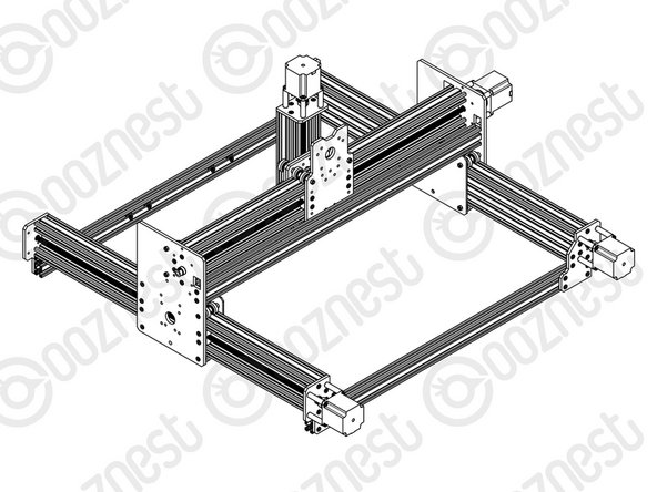
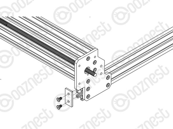
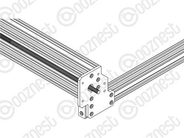
Slide a C-Beam-750mm through each set of wheels on the X-Gantry-Assembly. The Y ACME-Screws go inside the ‘C’ Channel.
-
Rest the ends of the C-Beam-750mm on 2 x V-Slot-2040-745mm’s. The ends of the extrusions should be flush with the sides of each other.
-
-
-
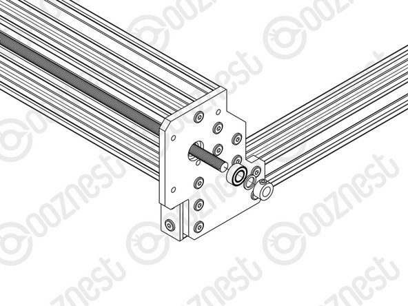
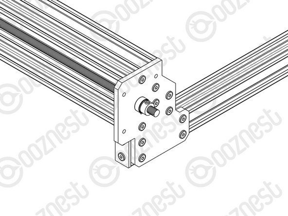
Double check you have identified the correct plates. The Y-End-Plate-Left oriented like the picture has the bearing recess facing outwards. The Y-End-Plate-Right is a mirror of this.
-
If possible while carrying out the below steps get a second person to hold the machine square.
-
Slide the X-Gantry-Assembly to the front, and attach a Y-End-Plate-Left to the front left corner, first using 4 x M5-Low-Profile-15mms, which screw into the tapped holes on the C-Beam-750mm.
-
Insert 2 x Tee-Nuts into the front facing top and bottom slots of the V-Slot-2040- 745mm. Adjust the Tee-Nuts so they line up with the holes on the Y-End-Plate-Left.
-
Secure the Y-End-Plate-Left to the V-Slot-2040-745mm using 4 x M5-Low-Profile- 12mms. Ensure the end of the V-Slot-2040-745mm is flush with the side of the C Beam-750mm.
-
Square the base, and repeat for the Y-End-Plate-Right on the opposite end of the front V-Slot-2040-745mm.
-
Slide the X-Gantry-Assembly to the back. Square the base, and repeat all the above for the back V-Slot-2040-745mm.
-
-
-
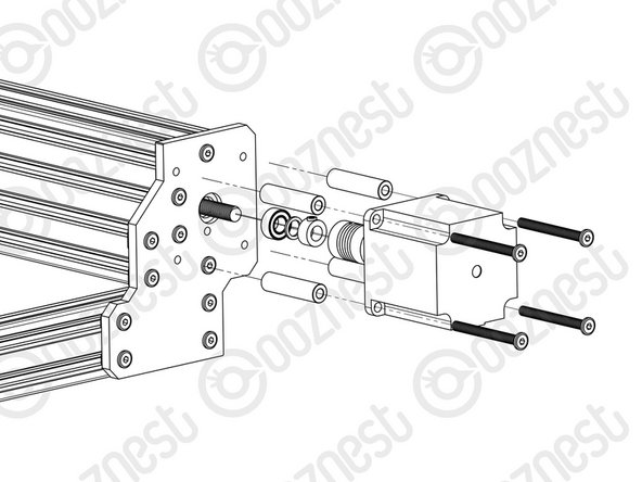
Adjust the left Y-ACME-Screw (as if looking from the front) so roughly 10mm is protruding from the Y-End-Plate-Right at the back of the machine. Slide onto the end a 688zz-Bearing, 8mm-Shim and 8mm-Clamping-Collar, and inset the 688zz-Bearing into the recess on the Y-End-Plate-Right.
-
Slide the 1/4” side (the side with the smallest hole) of the Flexible-Coupler onto the shaft of the NEMA23-Stepper-Motor. Don’t tighten it down at this point.
-
Attach the NEMA23-Stepper-Motor to the threaded holes on the Y-End-Plate-Right using 4 x M5-Low-Profile-50mm bolts and 4 x Aluminium-Spacer-40mms. Adjust the Y-ACME-Screw so it is touching the NEMA 23-Stepper-Motor shaft.
-
Orient the NEMA23-Stepper-Motor so the wire is facing downwards.
-
While pushing the 8mm-Clamping-Collar against the 8mm-Shim and 688zz-Bearing into the recess on the Y-End-Plate Right, tighten the clamping bolt on the 8mm-Clamping-Collar.
-
Tighten the grub screws on the Flexible-Coupler. Make sure one is on the flat portion of the motor shaft.
-
Repeat for the final NEMA23-Stepper-Motor attaching it to the Y-End Plate-Left on the back right of the machine.
-
-
-
At the front of the machine, onto the two Y-ACME-Screws protruding from the Y-End-Plates slide on a 688zz-Bearing, 8mm-shim, and a 8mm-Clamping-Collar.
-
While pushing the 8mm-Clamping-Collar against the 8mm-Shim and 688zz-Bearing into the recess on the Y-Plate-End-Plates, tighten the clamping bolt on the 8mm-Clamping-Collar.
It would be helpful to mention how to tension the lead screws on the larger machines before tightening the collars on this end
Christiaan - Resolved on Release Reply
It would be helpful to mention how to tension the lead screws on the larger machines before tightening the the collars on this end.
Christiaan - Resolved on Release Reply
-
-
-
Attach an End-Cap to front left end of the V-Slot-2040-745mm using 2 x M5-Low-Profile-8mm bolts.
-
Repeat this for the other 3 x End-Caps on the other bare ends of the V-Slot-2040-745mms.
-


Thanks for following the guide. Any issues, please contact us!
Thanks for following the guide. Any issues, please contact us!
Cancel: I did not complete this guide.
37 other people completed this guide.

6 Comments
The Y screws don’t actually protrude beyond the Y end plates (on the front face of the machine). I thought I was supposed to push the screw up against the motor shaft? I must have done that part incorrectly because the screw simply isn’t long enough to attach a lock collar on the opposite end. Other than that, this machine came together pretty nicely!
Tyler Ives - Resolved on Release Reply
I found that there is not much room to fit in the clamping collar and flexible coupling on the Y axis drives. The flexible coupling is pushed right up against the motor meaning that the grub screw is past the flat on the motor shaft. It seems to function ok but could probably do with 5mm longer bolts and spacers to be on the safe side.
Paul Clements - Resolved on Release Reply
You can’t beat having the info in the instructions that you are following- not having to remember/refer to numbers elsewhere…
Also, before putting on the end caps you need to insert the correct number of tee nuts in the top inside face ( 4,6 or 8), to attach the spoiler board supports in the next section. (it becomes the bottom of the three per bracket.)
Mike Magnay - Resolved on Release Reply
The dimensions used are for the 750 x 750 machine. It would be clearer if alternative dimensions were given also.
e.g. “Slide a C-Beam-750mm (1000mm, 1500mm) through each set…”
Mike Magnay - Resolved on Release Reply
Hi Mike,
Thanks for your comment, We have a full breakdown in the Introduction pages did you give it a read through? I can find a way to make it clearer in the introduction of the guides, They display specific lengths in the guide for the 750 x 750mm size due to it being the most popular…