
-
-
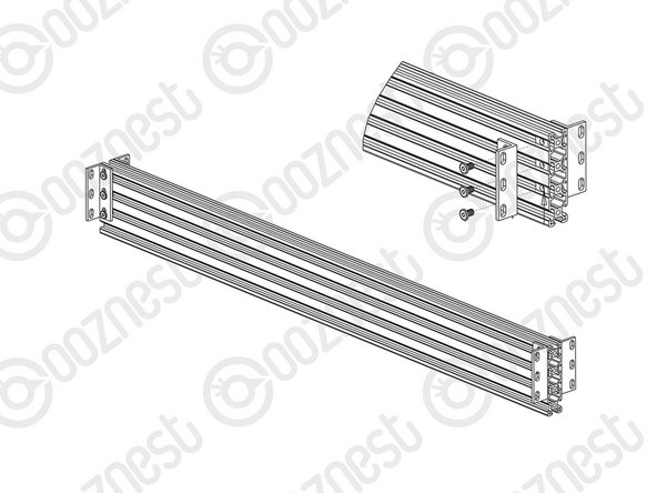
With a V-Slot-2040-665mm in hand, designate which sides are the top facing and outward facing. On the outward face, insert 2 x Tee-Nuts in both the upper and lower slots. On the top face, insert 2 x Tee-Nuts.
-
If you have a machine with a 750mm X-Axis, on the inward face, insert 4 x Tee-Nuts in both the upper and lower slots. 6 x Tee-Nuts for a 1000mm X-Axis, and 8 x TeeNuts for a 1500mm X-Axis.
-
Insert the V-Slot-2040-665mm in between both C-Beam-750mm’s so it sits on top of the front V-Slot-2040-745mm. The outward face should be against the Y-End-Plates.
-
Repeat for the back V-Slot-2040-665mm.
-
-
-
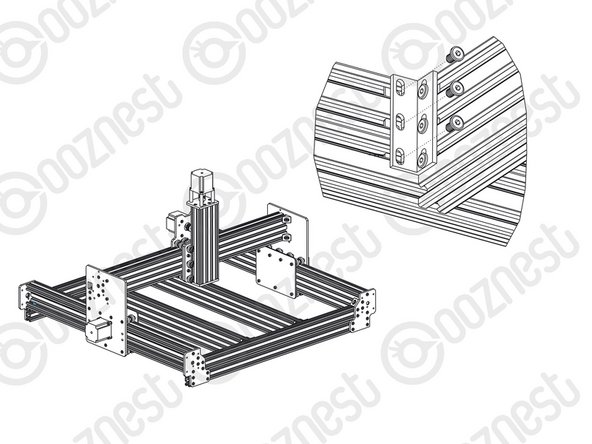
Align the Tee-Nuts in Step 1 with the two holes on the Y-End-Plate-Left. Use 2 x M5-Low-Profile-12mm bolts to secure the extrusion.
-
Repeat for the other 3 x Y-End-Plates.
-
Attach one side of an Angle Corner to the inside face of the right hand C-Beam750mm using a M5-Low-Profile-8mm bolt and a M5-Drop-In-Tee-Nut. Attach the other side to the V-Slot-2040-665mm using a M5-Low-Profile-8mm bolt and a Tee-Nut that was inserted into the top face in Step 1.
-
Secure the Angle-Corner tightly in the corner between the C-Beam-750mm and V-Slot-2040-665mm while the machine is held square.
-
Repeat for the other 3 corner joints between the C-Beam-750mm and V-Slot 2040-665mm rails.
-
-
-
Insert 3 x Tee-Nuts into the top 3 slots of the V-Slot-2080-710mm.
-
With a Universal-Bracket-Triple in hand, notice that the holes down one side are not the same distance away from the corner edge as the holes on the other side. The side with the holes closest to the corner edge should go against the V-Slot-2080-710mm.
-
With the top of the Universal-Bracket-Triple flush with the top of the V-Slot-2080- 710mm, secure it using 3 x M5-Low-Profile-8mm’s.
-
3 more Universal-Bracket-Triples need to be attached to the V-Slot-2080-710mm repeating the above.
-
If you have a machine with a 750mm X-Axis repeat the previous points for one more V-Slot-2080-710mm.
-
2 more times for a 1000mm X-Axis.
-
3 more times for a 1500mm X-Axis.
-
-
-
If you have a machine with a 750mm X-Axis insert 4 x Tee-Nuts in to the top slot on the inward face on both the front and back V-Slot-2040-745mm’s.
-
6 x Tee-Nuts for a 1000mm X-Axis.
-
8 x Tee-Nuts for a 1500mm X-Axis.
-
The Spoilerboard-Support-Assemblies should be evenly spaced along the X-Axis of the machine. For a machine with a 750mm X-Axis, from the inside edge of the Angle-Corner make two marks, one 209mm in, and another 418mm in.
-
Do this on both the front and back V-Slot-2040-665mm’s.
-
These marks should have 219mm spacing for a 1000mm X-Axis, and 275mm spacing for a 1500mm X-Axis.
-
Bring the previously assembled Spoilerboard-Support-Assemblies down in between the front and back sides with the Universal-Bracket-Triple towards the top, and line up the center of the V-Slot-2080-710mm’s with the center marks made in Step 4.
-
Line up all the previously inserted Tee-Nuts with the holes on the Universal-L-Brackets-Triple’s, and secure the Spoilerboard-Support Assembly using 12 x M5-Low-Profile-8mm’s on each Spoilerboard-Support-Assembly
-


Thanks for following the guide. Any issues, please contact us!
Thanks for following the guide. Any issues, please contact us!
Cancel: I did not complete this guide.
17 other people completed this guide.

3 Comments
As mentioned by Simon Millyard, in step 3 it is only possible to secure the bracket using ther top 2 bolts only as the bottom one is not correctly aligned. So I am also continuing with only the top 2 bolts secured.
By step 4 I had run out of tee nuts, so did it mean to use drop in tee nuts instead ? I also used spacing of approximately 220mm centres as this is more evenly spaced.
Step 3. I can only get 2bolts into the Universal Bracket Triple to fir into the V slot for the spoiler board support bracket. The pitch of the slots in the bracket does not match the pitch of the V slot. Any suggestions please? I am proceeding with just two bolts per bracket.
Simon Millyard - Resolved on Release Reply
Step 4 part 1-
This slot is not accessible, due to the fitting of the cover plates in the previous section. I have suggested in that section that these tee nuts are added before fitting the cover plates.
Mike Magnay - Resolved on Release Reply