Reputation over time
It looks like this user hasn't gained any reputation yet.
Once they have, you'll be able to view a graph of their reputation gained over time.
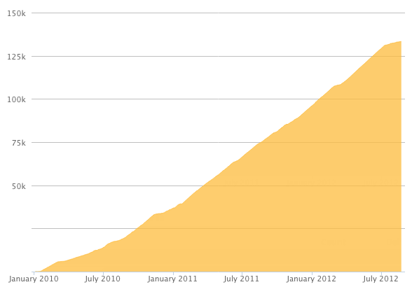
Here's a preview of what the graph will look like:
Reputation Breakdown
No reputation gained yet.
671
How do you loosen the nut-blocks? I can’t see an easy way to do this short of taking the machine apart. There must be an easier way….
You may find that the hinges do not fit very well. I reamed out the hinge holes with a 7.5mm drill to get the hinges to fit.
I hope you will all forgive me here
There is a Calvin and Hobbes strip where Calvin’s dad is fixing the sink. He has some instructions, the first of which is “memorise this handy list of expletives and be sure you know how to use them” ….. So I am writing this having completed the installation of the kit.
If you are upgrading an existing Workbee with the Duet controller exposed you may find that getting sufficient cable into the box is very marginal. If this is the case with your Workbee then cut every cable tie before you start and make sure you can get every millimeter of cable you can. This especially applies to the Green (5) stepper cable. Getting everything to stretch into the box without undue strain on the board takes some doing and would try the patience of a saint.
The kit is (as are all of the Ooznest kits) very complete however if you have a few extra cable ties you can afford to chop a few as you wrestle with the loom.
It can be done but take some time.
I am indebted to Ryan for his help regarding this. I noticed (after several months of operation) that if I cut a 500mm x 500mm square one side had a slightly different length to the other. Left hand side in Y axis 499mm, Right hand side in Y axis 500mm. This is a very small error but this is CNC so should be right. Changing the tension slightly changes the steps per mm. To test for this cut a square as detailed and measure with the best accuracy possible. Aim to get both Y sides equal, the absolute distance can then be adjusted by changing the steps per mm value. I understand that having a command to adjust the steps for each Y motor is being looked at.
Wow! Got here! All working as expected, just making sure all the details are correct but essentially it looks at it should do. I still have a lot of nuts bolts and bits left over - I was concerned I missed something but that seems to be a bit thoughtful excess to assist the builder. The part that gave the most trouble was configuring the Duet board , I have some sympathy for Ooznest here as getting unknown computers to talk to each other especially with a plethora of operating systems out there is always problematic. Thank goodness it didn’t need Linux… Anyway good job, many thanks.
Might be a good idea to install Y-Axis-Moving-End-Assembly at this point. I know this is not covered until the electrical work but the screws are very fiddly.
My Y-Axis-Fixed-End-Assembly had a large chunk of 3d printer material (presumably the support during the printing process). This pulls away very easily but fouls the end cap if not done.
The above diagram is slightly misleading as it shows the End-Caps in place. End-Caps turn up in Step 6 of “6 Spoiler Board Support Extrusions”. Tee-nuts need to be inserted so the plates are left off here. M5-Low-Profile-8mm bolts are used to secure the End-Caps.
You can add the touch probe connector at this point. Open ANOTHER window with the touch probe instructions…!
Totally agree with the comment regarding natural direction of the z limit switch wires. Take care first of all not to chew them up when you put your c beam into place (I did…) I had to resolder the wires but did so so that they headed out sideways instead of up towards the beam.
Page 1 of 2
Next