Reputation over time
It looks like this user hasn't gained any reputation yet.
Once they have, you'll be able to view a graph of their reputation gained over time.
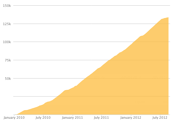
Here's a preview of what the graph will look like:
Reputation Breakdown
No reputation gained yet.
862
For those wondering, they go into the “back” of the C-Beam (the closed side, not the open side of the C). In terms of the channels you need, it’s the two most outer channels.
These images make it difficult to understand where the Tee-Nuts need to go. For those wondering, they go into the “back” of the C-Beam (the closed side, not the open side of the C). In terms of the channels you need, it’s the two most outer channels.
Hold on adding the NEMA23-Motor until you get to Section 4, Step 3. By having the motor attached now, you will struggle to attach the ACME Screw to this motor in a later stage, and have to disassemble it anyway. There simply isn’t enough clearance later on to make sure that the ACME Screw is correctly connected to the motor shaft, so it’s easier to add the motor later on.
For anyone having any questions about which way is “upwards” or “downwards” on the F688ZZ-Bearing, the narrow part of the bearing slots neatly into the Z-End-Mounts (to fit snugly into the mount and hold the ACME screw perfectly in place). You basically need both narrow parts of the bearings to be pointed away from the carriage in the middle. The 8mm-Shim makes contact with the wider part of the bearing.
To position the motor shaft and ACME screw about halfway inside the Flexible-Coupler, you can use a torch and shine it through the sides of the Flexible-Coupler to see where the shafts are inside (by watching for the silhouette of each shaft through the helical gaps in the Flexible-Coupler). I moved both into contact at the halfway point, and then pulled the ACME screw back about a millimetre so that there could be some play.
Pulling a useful comment from a previous version, to adjust the set screw in the Anti-Backlash-Nut-Block, you need to lower the carriage all the way to the bottom (furthest from the stepper motor) and use a long allen key to reach in. You’ll likely need a torch to see it. Removed all play for me with about two turns.
This picture seems to be in a different orientation to the one shown in 5. Wire Routing (Step 2). This image makes it look like the raised ridge is on the left, whilst the photograph shown in a later step suggests the ridge is to the right. I’ve gone with the photograph and will come back and correct this comment if that photograph isn’t the right orientation.
Also, the supplied limit switch wires came into light contact with my C-Beam when that was installed. All it took was some slight pressure to make sure that the switch-wire connection wasn’t so proud, but worth watching out for to prevent wear on the wire.