
-
-
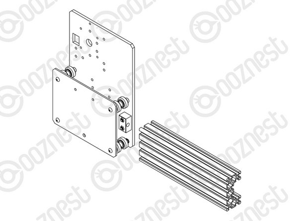
Attach 2 x Nut-Blocks to a Y-Plate-Outer using 4 x M5-Button-Head-Bolt-25mm & 4 x M5-Nyloc-Nuts.
-
Keep these bolts loose so the Nut-Blocks can still move side to side.
-
-
-
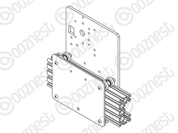
Assemble the bottom right Solid-Wheel set first. Insert a M5-Button-Head-Bolt-60mm through the Y-Plate-Inner
-
On to the bolt add an Eccentric-Spacer-6mm. (Rounded portion into the Y-Plate-Inner)
-
Then add a Precision-Shim - ->- - Solid-Wheel - ->- - Aluminium-Spacer-9mm - ->- - Solid-Wheel - ->- - Precision-Shim
-
Add an Eccentric-Spacer-6mm then a Y-Plate-Outer. (Rounded portion of the Eccentric-Spacer-6mm goes into the Y-Plate-Outer)
-
On the outside of the Y-Plate-Outer add onto the bolt a Precision Shim then a M5-Nyloc-Nut. Only slightly thread on the M5-Nyloc-Nut.
-
Repeat the above for the other Solid-Wheel set on the bottom row.
-
Repeat for the 2 x Solid-Wheel sets on the top row, but use a Aluminium-Spacer-6mm instead of each Eccentric-Spacer-6mm.
-
The M5-Nyloc-Nuts can now be tightened. Ensure that each Solid-Wheel still rotates freely.
Is there any detriment to putting the eccentric spacers on the top row rather than the bottom?? I put mine on the bottom as per the guide and spent a few hours today skinning my knuckles trying to adjust the eccentric gap under the extrusions....the amount of travel possible with the supplied spanner is probably less than 1/16 of a rotation
elliot parfitt - Open Reply
Hi Elliot,
We recommend keeping eccentric spacers on the bottom so the machine's weight rests on the solid aluminum spacers, ensuring stability. Adjusting them can be tricky, but using a slim spanner or rotating the gantry can help.
If you need further assistance, feel free to reach out to us at https://ooznest.co.uk/help/
Cyndy -
The top 4 holes on one of my inner Y plates are too small so the M5 bolts will not pass through.
Emailed support.
waynechurchill@sky.com - Resolved on Release Reply
Agree with Roy Cruise, so much easier to build with the Y plate on it's back, just ensure the eccentrics are seated before tightening.
Laurie Wilson - Resolved on Release Reply
Us chaps could do with longer and thinner finger nails to pick up these shims!!
patkempe@uwclub.net - Resolved on Release Reply
If you guys are having issues pushing the bolt through the wheels you made, just check the bearings are pushed firmly into the plastic wheel housing. I’ve found if they aren’t perfectly aligned, then the bolt will not go through. Its good to check all the assembled wheel units can have the bolt passed through them before assessembling the Y plates
Paul Orbell - Resolved on Release Reply
When I did the second assembly I put the Y-plate-inner down on the table and the four screws and then did all four screw-wheel-assembly at the same time. Did not really understand why there was a need to do the four screw-wheel-assembly sequentially.
Hi Emil,
Thanks for tip. Yes, you can do it that way. I think it was written as above as it is easier to convey in images and words. Robert
Robert -
Typo at bullet point one. Should read Assemble. Not a big deal but challenged my tired grey matter.
thesteveearl@icloud.com - Resolved on Release Reply
Hi Rob,
Thanks for your email.
It should be 6mm spacer, shim, wheel, 9mm spacer, wheel, shim, 6mm spacer.
(No shim either side of the 9mm spacer)
Robert
Before I tighten these nuts can I confirm the wheel configuration is, 6mm spacer, shim wheel, shim, 9mm spacer, shim, wheel, shim, 6mm spacer.
the bit i’m questioning is there a shim either side of the wheel ?
Rob Thompson - Resolved on Release Reply
-
-
-
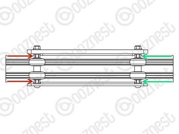
On the hexagonal portion of the Eccentric-Spacer-6mm, there will be a face that is marked with ‘6mm’.
-
Using a 8mm spanner, rotate each Eccentric-Spacer-6mm so that this face is facing downwards. (Doing this maximises the gap between the top and bottom row of Solid-Wheels)
-
Insert Extrusion-D in-between the two rows of wheels. Turn the assembly upside down so Extrusion-D is sitting on the top row of Solid-Wheels.
-
Rotate both Eccentric-Spacer-6mms on one set of Solid-Wheels until there is a small amount of friction between the Solid-Wheels and Extrusion-D
-
Repeat for the other set of Solid-Wheels.
-
Slide Extrusion-D back and forth. This should require a small amount of force, and all Solid-Wheels should spin.
-
Check there is no wobbling of Extrusion-D. Once happy, double-check the tightness of the M5-Nyloc Nuts and remove Extrusion-D.
-
Try to get all the Solid-Wheels touching Extrusion-D as best as possible. If not, it is not a problem, we will check the Eccentric-Spacers-6mms again once the machine is built.
I found it much easier to assemble all 4 solid wheel assemblies at once with the inner plate lying flat on its back holding the bolts in place. Otherwise its fiddly and hard to get the shim and 6mm spacer on the last one. Once all 4 are done place the outer plate on top and add the shims and nuts. Just make sure the eccentric nut has located properly before tightening
The 8mm spanner mentioned at bullet point 2 is provided (in the ‘extras’ box).
thesteveearl@icloud.com - Resolved on Release Reply
-
-
-
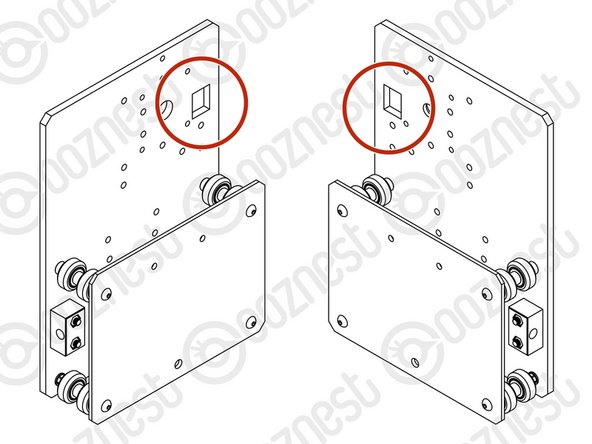
Repeat Steps 1-3 for another Y-Plate Assembly. It should be a mirror image of the previous assembly.
-
Ensure the square cut out on the Y-Plate-Outer is at the back.
Hi Bart,
Thanks for your message. Extrusion D is used on a later guide, so you are ok to remove it.
Thanks for your feedback!
Hi Robert,
I meant maybe you can add that to the instructions so the next person isn’t left wondering about the same thing! :-)
Bart
Excellent instructions. You could perhaps clarify two things:
a) Extrusion-D at this stage is only used to adjust wheel spacing, there is only one of them, and it’s ok to remove it from the first Y-plate to insert into the second. Nothing major but I started looking for a second Extrusion-D when adjusting the wheels on the second plate.
b) Reword instructions for step 4 with emphasis on the mirror image aspect. It currently says “repeat steps 1 to 3” but taking this literally would result in two identical copies of the plates. Perhaps say that the square cutout should be at the front when assembling the second plate?
Hi Bart,
Thanks for your message. Extrusion D is used on a later guide, so you are ok to remove it.
Thanks for your feedback!
Robert -
-
-
-
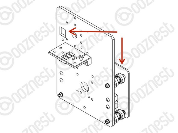
A Drag-Chain-Mount needs to be attached to the second Y-Plate-Outer.
-
Make sure you have the correct Y-Plate-Outer.
-
The square cut out on the Y-Plate-Outer is at the back with the wheels on the opposite side.
-
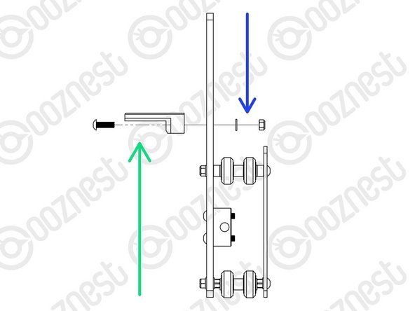
Insert 2 x M5-Button-Head-Bolt-16mms through the Drag-Chain-Mount, then through the Y-Plate-Outer.
-
Then add a 2 x Precision-Shims and 2 x M5-Nyloc-Nuts on the opposite side of the Y-Plate-Outer.
-
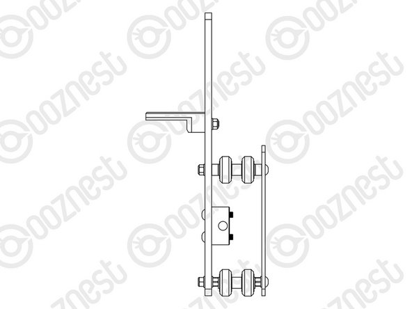
Moving forward this will be known as the Y-Carriage-Left.
-
The other one will be known as the Y-Carriage-Right.
-
-
-
The Y-Carriages can be put to one side until later.
-
Guide Complete - Proceed to 3. X-Carriage Assembly
-


Thanks for following the guide. Any issues, please contact us!
Thanks for following the guide. Any issues, please contact us!
Cancel: I did not complete this guide.
102 other people completed this guide.

3 Comments
On page 3 it incorrectly implies that you use ‘eccentric’ spacer 6mm on the top & bottom wheel sets - it should say ‘aluminium’ spacer 6mm (I think?!)
Jim Cooper - Resolved on Release Reply
my advice here would be not to leave the nut blocks too loose - just 'off-tight' is fine. I made the mistake of having them really loose (rattling around) and that gave me massive headaches when it came to threading the lead screws through
elliot parfitt - Open Reply
One of my Nut-Blocks has the lead screw hole oriented to the wrong offset.
Emil - Resolved on Release Reply
Hi Emil,
Sorry about that, please get in touch and we can replace it: https://ooznest.co.uk/help/
Robert -
My Nut-Blocks where not equally. One had an offset in the hole creating a lot of tension on the lead screw.
Emil - Resolved on Release Reply