Reputation over time
It looks like this user hasn't gained any reputation yet.
Once they have, you'll be able to view a graph of their reputation gained over time.
Here's a preview of what the graph will look like:
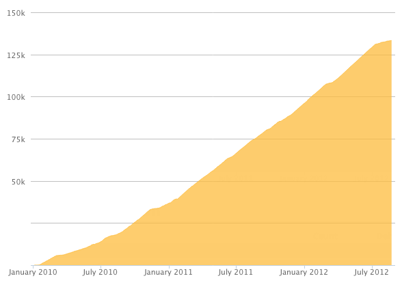
Reputation Breakdown
No reputation gained yet.
1415
Except for the Z axis, I’ve found that some of the wheels have no friction on the extrusion at all. Adjusting the eccentric spacer to give them some friction results in the opposite wheel (on the up or down side) being pretty much rock-solid (or at least barely movable by hand). Is that supposed to be like that?
The magnet trick works quite well!
After tensioning the lead screws I found it impossible (for the Y axis anyway) to reinsert the flanged bearings back into the holes as the lead screws were slightly off-centre. The only way I could make this work was by leaving the bearings in the holes while doing the tensioning.
The published footprints of the machines should be updated to take into account mounting of the Y-drag chain to the bench. I had some 770x770x18 MDF cut for my 750x750 machine and when it came to screwing down the drag chain there wasn’t enough room. So now my machine overhangs one side of the MDF board by a couple of cm so that the drag chain can be mounted on the other side.
It would be useful to know roughly what length of each of the wires needs to extend into the controller box. Trying to pull out more wire through the tightened cable sleeve and the drag chain is a nightmare.
Same problem as above: filed the holes out a bit using a round file. Some of the counterbores were oval too and the bolt heads didn’t fit so had to scrape them out a bit. Might be an idea to slightly increase their diameter in the 3D model to compensate for this.
Hi Robert,
I went all the way back from step 7, removed the X and Y gantries and started the base afresh. The two outer Extrusion-Cs are now within less than 0.1 mm (caliper) of 80 mm from the ends of the Extrusion-As. I bought a proper engineer’s square (turns out the £5 job from B&Q I already had wasn’t the squarest thing in the world) and checked three of the inner A-C angles by removing the inner L-brackets temporarily (they make it impossible to properly fit in the square). Three of the angles are as square as they will ever be. Geometrically speaking, the fourth one should then also be perfect but it’s very slightly off (a very tiny amount though, barely noticeable). This is as good as I’m ever gonna get this! The diagonals are now spot-on too so I’m going with this! Maybe I should’ve done this properly to begin with… You live and learn… :-)
Bart
The diagonals on my 750x750 machine are off by just under 2 mm. Hopefully that’s good enough as I have a feeling I would just make it worse if I tried to adjust it…
Updated URL for the thing in my last comment: https://www.printables.com/model/291541-...
I had the same issue. Another way around it is to put both bolts into the angle corner first BEFORE tightening either of them.
Page 1 of 2
Next