
-
-
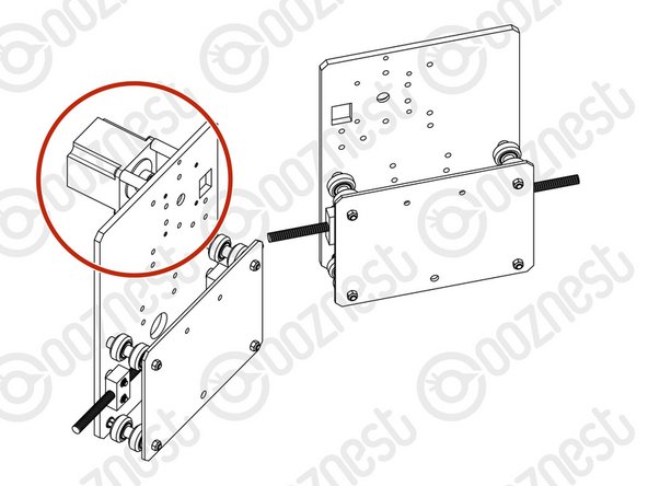
Attach 2 x ACME-Nut-Blocks to the Y-Plate-Right using 4 x M5-Low-Profile-25mm bolts & 4 x M5-Nyloc-Nuts. On each bolt, in-between the ACME-Nut-Block and Y-Plate-Right, there should be an Aluminium-Spacer-3mm and a Precision-Shim. Only loosely tighten these bolts so the ACME-Nut-Blocks can still move side to side.
-
Double check you have the correct plate. Orientated as the picture, there should be no bearing recess on the same side as the ACME-Nut-Blocks.
-
Thread a Y-ACME-Lead-Screw through both ACME-Nut-Blocks. Tighten the bolts holding one of the ACME-Nut-Blocks, making sure it is square to the Y-Plate-Right.
-
To remove any backlash, pinch the loose ACME-Nut-Block towards the previous one, and tighten the bolts holding it. Leave the Y-ACME-Lead-Screw threaded through the ACME-Nut-Blocks.
-
-
-
First attach the bottom right wheel set; insert a M5-Low-Profile-60mm bolt through the Y-Plate-Right-Assembly from the back. On to this bolt, add an Eccentric-Spacer-6mm, Precision-Shim, Solid-V-Wheel-Xtreme-Assembly, Aluminium Spacer-9mm, Solid-V-Wheel-Xtreme-Assembly, Precision Shim, and a Eccentric-Spacer-6mm in this order.
-
Next, add a Y-Plate-Inner onto the top of this assemblage, and then slightly thread on a M5-Nyloc-Nut. The rounded portion of the Eccentric-Spacer-6mm should be inserted into the hole on either the Y-Plate-Left-Assembly or Y-Plate-Inner (depending on which side it is on).
-
Repeat for the other wheel set on the bottom row corner.
-
Repeat for the 2 wheel sets on the top row, however for these sets use Aluminium-Spacer-6mms instead of Eccentric-Spacer-6mms.
-
Once all of the wheels are attached the M5-Nyloc-Nuts can be tightened down. Ensure that the Solid-V-Xtreme-Wheels can still rotate freely. On the hexagonal portion of the Eccentric-Spacer-6mm, there will be one face that is marked with ‘6mm’.
-
Using a spanner, adjust each Eccentric-Spacer-6mm so that this face is facing downwards. Doing this maximizes the gap between the top and bottom row of wheels.
-
-
-
Run any piece of C-Beam extrusion in-between the two rows of wheels. Initially, there may be a small amount of play between the C-Beam and wheels. Turn the assembly upside down so the C-Beam is sitting on the row of wheels with the Aluminium-Spacer-6mms.
-
Starting with one pair of wheels, adjust both Eccentric-Spacer-6mms down onto the C-Beam Extrusion until there is a small amount of friction between both wheels and the C-Beam Extrusion.
-
When adjusting the pair of Eccentric-Spacer-6mms ideally they should be adjusted identically. However, sometimes one will need to be adjusted slightly more than the other to get both wheels engaged with the C-Beam extrusion.
-
Repeat for the other pair of wheels with eccentric spacers.
-
Slide the C-Beam extrusion back and forth through the wheels. This should require a small amount of force, and all wheels should spin as it rolls. Also check there is no wobbling of the extrusion. Once happy, double check the tightness of the M5-Nyloc Nuts.
-
-
-
Repeat the this section for the Y-Plate-left. As seen above it should be a mirror image of the Y-Plate-Right-Assembly.
-
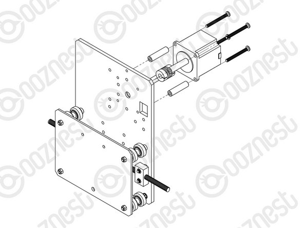
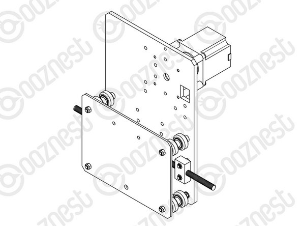
A NEMA23-Stepper-Motor needs attaching to the Y-Plate-Left. See pictures 2 & 3.
-
Slide the 1/4” side (the side with the smallest hole) of the Flexible-Coupler onto the shaft of the NEMA23-Stepper-Motor. Don’t tighten it down at this point.
-
Attach the NEMA23-Stepper-Motor to the threaded holes on the Y-Plate-Left using 4 x M5-Low-Profile-50mm bolts and 4 x Aluminium-Spacer-40mm’s.
-
Orient the NEMA23- Stepper-Motor so that the wire is towards the back of the Y-Plate-Left (the side closet to the small rectangle opening).
-


Thanks for following the guide. Any issues, please contact us!
Thanks for following the guide. Any issues, please contact us!
Cancel: I did not complete this guide.
54 other people completed this guide.

10 Comments
Same here, eccentrics fully loose, c-beam quite tight. Mobility seems good though.
Exactly the same here. Practically no way to set the gaps
I have received a new set of eccentrics but unfortunately it is more or less the same !!!!
Could be a problem with the holes distances on the plates ??
Mirco -
Even with the eccentric nuts st to fully loose, the C-beam is still tight. Is this normal?
Brian Trowbridge - Resolved on Release Reply
Same. Gaps are fully open but the C-Beam is very tight, went in with a bit of a shove mind. Hoping for the best it might just mean the adjustment allows for future bedding in.
It would be useful to say which packets/boxes the parts are in to save me opening everything.
Brian Trowbridge - Resolved on Release Reply
Hi there, i do not believe you have included all the parts. In the diagram for the Y PLATE inner and left. It shows there to be a Y-ACME-Screw for each set up..
I have not recieved this in my kit. i have only recieved one screw labled Z-acme- screw.
Nothing seems to be in the correct boxes. do you have an inventory list of everything i should hae in this kit please?
i cannot carry on with my build until this is resolved. Very disappointed after spending over £2000
jimi barker - Resolved on Release Reply
You have probably figured this out by now but its not the Z acme-screw you should be using,, thats for the Z axis.. so you only need one of those. The Y-acme screws are the longer ones. the diagram is just showing a section of the screw to illustrate where it goes! My machine is 1500 x 1500mm so the 3 longer ACME screws weren’t labelled as they are all the same size!
I'‘m in the process of assembling workbee 1500x1500. In this instruction 4 pair of wheels are shown. In the Openbuilds youtube video for workbee 1000x1000 they are using 3 pairs of wheels more (1 pair more on the bottom and 2 pairs more in the upper side). Shouldn’t I have it too in such big machine?
Y-Plate left is mentioned in here, does it mean Y-Plate-Right?
David Pye - Resolved on Release Reply
Hi David, Thanks for noticing this - I have updated this guide.
Ryan Christy -