-
-
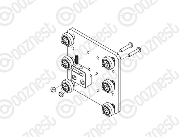
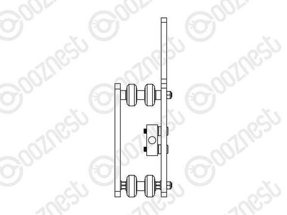
First attach the top right wheel, insert a M5-Low-Profile-30mm through the Z-Plate from the back (the back is the side with the insets). On to this, add an Eccentric Spacer-6mm, Precision-Shim, Solid-V-Wheel-Xtreme-Assembly and a M5-Nyloc-Nut in this order.
-
The rounded portion of the Eccentric-Spacer-6mm should be inserted into the hole on the Z-Plate. The assembly can be tightened, ensuring the Solid-V-Xtreme Wheel can still rotate freely.
-
Repeat the other two wheels on the right row.
-
Repeat for the 3 wheel sets on the left row, however for these sets use Aluminium-Spacer-6mms instead of Eccentric-Spacer-6mms.
-
On the hexagonal portion of the Eccentric-Spacer-6mm, there will be one face that is marked with ‘6mm’. Using a spanner, adjust each Eccentric-Spacer-6mm so that this face is facing to the right. Doing this maximizes the gap between the left and right row of wheels.
-
-
-
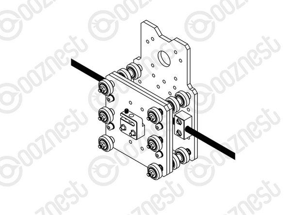
Run any piece of C-Beam extrusion in-between the two rows of wheels. Initially, there may be a small amount of play between the C-Beam and wheels. Turn the assembly so the C-Beam is sitting on the row of wheels with the Aluminium-Spacer-6mms.
-
Starting with an outside wheel, adjust the Eccentric-Spacer-6mm down onto the C-Beam Extrusion until there is a small amount of friction between the wheel and the C-Beam Extrusion.
-
Repeat this for the other outside wheel, and then for the middle wheel.
-
Slide the C-Beam extrusion back and forth through the wheels. This should require a small amount of force, and all wheels should spin as it rolls. Also, check there is no wobbling of the extrusion. Once happy, double check the tightness of the M5-Nyloc Nuts.
-
-
-
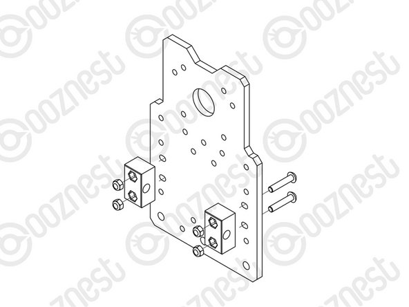
Attach the ACME-Anti-Backlash-Nut-Block to the Z-Plate using 2 x M5-Low-Profile-25mm bolts and 2 x M5-Nyloc-Nuts.
-
With the set screw provided with the ACME-Anti-Backlash-Nut-Block, screw it into the smaller threaded hole on the top of the ACME-Anti-Backlash-Nut-Block until it is just before the point of touching the surface on the opposite side of the gap.
-
The set screw will later be used to remove any backlash from the system.
-
Discard the nut left in the bag with the ACME-Anti-Backlash-Nut-Block.
-
-
-
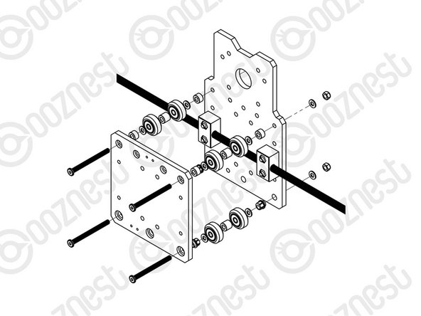
Attach 2 x ACME-Nut-Blocks to the X-Plate-Back using 4 x M5-Low-Profile-25mm bolts & 4 x M5-Nyloc-Nuts.
-
Only loosely tighten these bolts so the ACME-Nut-Blocks can still move side to side.
-
Thread the X-ACME-Lead-Screw through both ACME-Nut-Blocks. Tighten the bolts holding one of the ACME-Nut-Blocks, making sure it is square to the X-Plate-Back.
-
To remove any backlash, pinch the loose ACME-Nut-Block towards the previous one, and tighten the bolts holding it.
-
Leave the X-ACME-Lead-Screw threaded through the ACME-Nut-Blocks.
-
-
-
If you have the full kit version of the WorkBee, please complete Step 5 of 4. Limit Switch Assembly & Mounting.
-
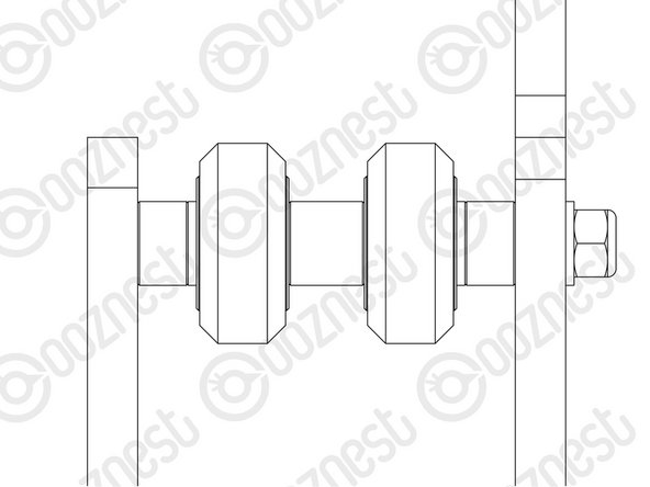
First attach the bottom right wheel set - insert a M5-Low-Profile-60mm bolt through the X-Plate-Front through the side with the insets. On to this, add an Eccentric Spacer-6mm, Precision-Shim, Solid-V-Wheel-Xtreme-Assembly, Aluminium Spacer 9mm, Solid-V-Wheel-Xtreme-Assembly, Precision Shim, and an Eccentric-Spacer 6mm in this order.
-
Next add the X-Plate-Back-Assembly onto the top of this assemblage, add a Precision-Shim and then slightly thread on a M5-Nyloc-Nut. The rounded portion of the Eccentric-Spacer-6mm should be inserted into the hole on either the X-Plate-Front or X Plate-Back-Assembly (depending on which side it is on).
-
Repeat for the other wheel set on the bottom row corner.
-
Repeat for the 2 wheel sets on the top row, however for these sets use Aluminium-Spacer-6mms instead of Eccentric-Spacer-6mms.
-
Once all of the wheels are attached the M5-Nyloc-Nuts can be tightened down. Ensure that the Solid-V-Xtreme-Wheels can still rotate freely. On the hexagonal portion of the Eccentric-Spacer-6mm, there will be one face that is marked with ‘6mm’.
-
In the same method as the Y-Plates, using a spanner, adjust each Eccentric-Spacer-6mm so that this face is facing downwards. Doing this maximizes the gap between the top and bottom row of wheels.
-
-
-
Run any piece of C-Beam extrusion in-between the two rows of wheels. Initially, there may be a small amount of play between the C-Beam and wheels. Turn the assembly upside down so the C-Beam WorkBee CNC Assembly 18 is sitting on the row of wheels with the Aluminium-Spacer-6mms.
-
Starting with one pair of wheels, adjust both Eccentric-Spacer-6mms down onto the C-Beam Extrusion until there is a small amount of friction between both wheels and the C-Beam Extrusion.
-
When adjusting the pair of Eccentric-Spacer-6mms ideally they should be adjusted identically. However, sometimes one will need to be adjusted slightly more than the other to get both wheels engaged with the C-Beam extrusion.
-
Repeat this for the other pair of wheels.
-
Slide the C-Beam extrusion back and forth through the wheels. This should require a small amount of force, and all wheels should spin as it rolls. Also check there is no wobbling of the extrusion. Once happy, double check the tightness of the M5-Nyloc Nuts.
-
-
-
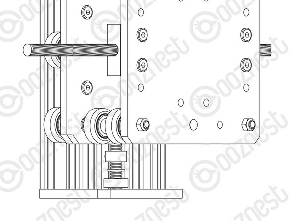
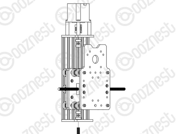
Mate the Z-Plate-Assembly to the X-Carriage-Assembly in the orientation seen above. In each of the 4 holes use a M5-Cap-Head-Bolt-12mm, Precision-Shim and a M5-Locking-Washer to secure the two assemblies together.
-
The M5-Locking-Washer should be against the Z-Plate. With the Precision-Shim in-between the M5-Locking-Washer and M5-Cap-Head-Bolt-12mm
-
Make sure the Z-Plate-Assembly is square to the X-Carriage-Assembly.
-
Do not over-tighten the M5-Locking-Washer. If over-tightened it will lose it's effectiveness.
-
-
-
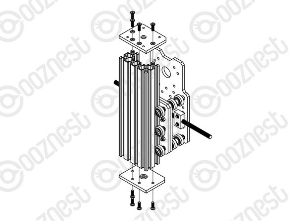
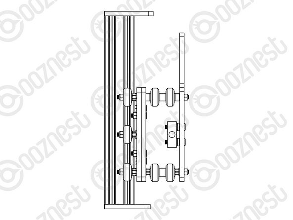
Slide the C-Beam-250mm through the Z-Wheels on the X-Carriage-Assembly.
-
Attach both of the Z-End-Mounts using 8 x M5-Low-Profile-15mm bolts.
-
Tighten the top Z-End-Mount bolts fully.
-
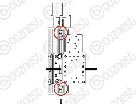
For the bottom Z-End-Mount, tighten the bolts fully, and then loosen by a single full turn (the reason for this will become clear later).
-
-
-
If you have an Ooznest XYZ Touch Probe, please complete Steps 1-3 of Assembling Your Original WorkBee XYZ Touch Probe
-
Slide the 1/4” side (the side with the smallest hole) of the Flexible-Coupler onto the shaft of the NEMA23-Stepper-Motor. Don’t tighten it down at this point.
-
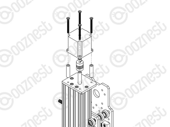
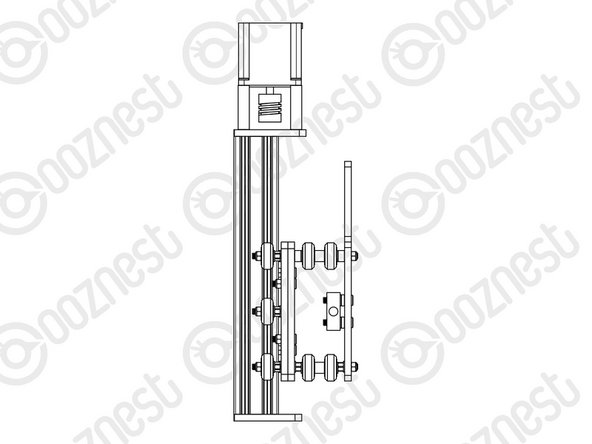
Attach the NEMA23-Stepper-Motor to the threaded holes on the Z-End-Mount using 4 x M5-Low-Profile-50mm bolts and 4 x Aluminium-Spacer-40mm’s.
-
Orient the NEMA23-Stepper-Motor so that the wire is towards the back of the X-Carriage-Assembly.
-
-
-
Please make sure you use the 8mm-Lock-Collar not 8mm-Clamping-Collar.
-
Slide the Z-ACME-Screw through the bottom Z-End-Mount. Then slide on a F688ZZ-Bearing (facing downwards), 8mm-Shim, and a 8mm-Lock-Collar in this order.
-
Thread the Z-ACME-Screw through the ACME-Anti-Backlash-Nut-Block, it may be hard to thread the Z-ACME-Screw through the ACME-Anti-Backlash-Nut-Block for the first time. Once through, slide on a 8mm-Lock-Collar, 8mm-Shim, and a F688ZZ-Bearing (facing upwards) in this order.
-
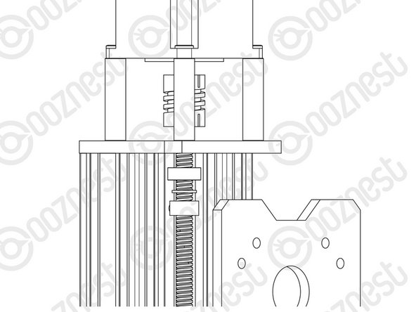
Fully thread through the Z-ACME-Screw until it is touching the NEMA 23-Stepper Motor shaft. Position the Flexible-Coupler so it is half on the Z-ACME-Screw and half on the NEMA23-Stepper-Motor shaft. Once in position, tighten the screws on the Flexible-Coupler.
-
Make sure one is on the flat portion of the motor shaft
-
Slide the second F688ZZ-Bearing up the Z-ACME-Screw until it seats in the hole on the top Z-End-Mount, then slide up the 8mm-shim onto the bearing, and finally slide up 8mm-Lock-Collar so it is firmly against the 8mm-Shim and lock it in place using the grub screw on the side.
-
Repeat for the bottom Z-End-Mount.
-
Locate the four M5-Low-Profile-15mm bolts that were left a full turn from tight in Step 8. These can now be fully tightened. Doing this will remove any play that may be present.
-
-
-
Firmly hold the X-Carriage-Assembly, and check for any up and down play in the C-Beam-250mm. If there is any, this is due to backlash in the ACME-Anti-Backlash-Nut-Block. The set screw which was inserted in Step 3 into the ACME-Anti-Backlash-Nut-Block can be screwed downwards to remove this.
-
Do not over tighten this, as it can make the Z ACME-Screw difficult to turn. You can test this by rotating the Flexible-Coupler by hand.
-
It should require a small to medium amount of force. This will need to be rechecked once the router is attached, and periodically checked when in use.
-
Thanks for following the guide. Any issues, please contact us!
Thanks for following the guide. Any issues, please contact us!
Cancel: I did not complete this guide.
51 other people completed this guide.


