-
-
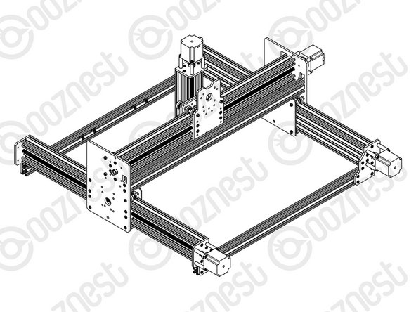
Slide a C-Beam-750mm through each set of wheels on the X-Gantry-Assembly. The Y-ACME-Screws go inside the ‘C’ Channel.
-
Rest the ends of the C-Beam-750mm on 2 x V-Slot-2040-745mm’s. The ends of the extrusions should be flush with the sides of each other.
-
-
-
If possible while carrying out the below steps get a second person to hold the machine square.
-
Slide the X-Gantry-Assembly to the front, and attach a Y-End-Plate to the front left corner, first using 4 x M5-Low-Profile-15mms, which screw into the tapped holes on the C-Beam-750mm.
-
Insert 2 x Tee-Nuts into the front facing top and bottom slots of the V-Slot-2040- 745mm. Adjust the Tee-Nuts so they line up with the holes on the Y-End-Plate.
-
Secure the Y-End-Plate to the V-Slot-2040-745mm using 4 x M5-Low-Profile- 12mms. Ensure the end of the V-Slot-2040-745mm is flush with the side of the C Beam-750mm.
-
Square the base, and repeat for the Y-End-Plate on the opposite end of the front V-Slot-2040-745mm.
-
Slide the X-Gantry-Assembly to the back. Square the base, and repeat all the above for the back V-Slot-2040-745mm.
This section is definitely a two person job - in fact, I think the entire build would best be completed by two people. After all, two heads are better than one and there have been several instances where I have misinterpreted the guides. With reference to all the extrusions: C beams and V slots - ensure there is no swarf in the threaded holes. I lightly tapped the extrusions on a tiled floor and vacuumed the threaded holes.
Stephen Hardman - Resolved on Release Reply
-
-
-
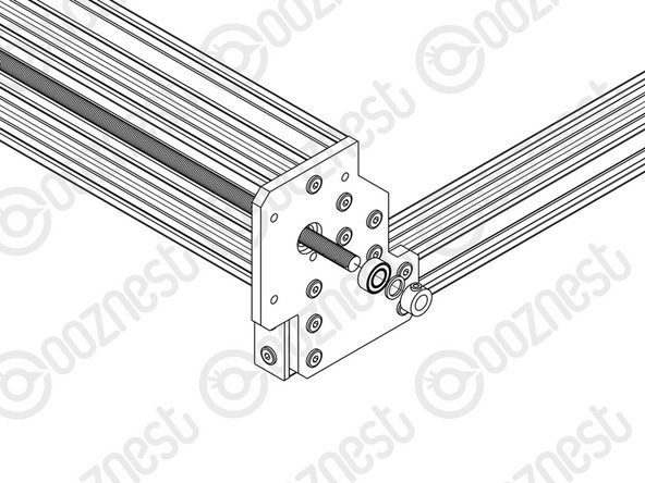
Adjust the left Y-ACME-Screw (as if looking from the front) so roughly 10mm is protruding from the Y-End-Plate at the back of the machine. Slide onto the end a F688zz-Bearing, 8mm-Shim and 8mm-Clamping-Collar, and inset the F688zz-Bearing into the hole on the Y-End-Plate.
-
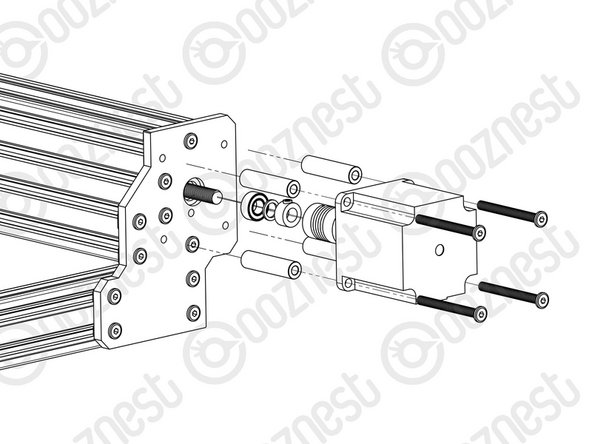
Slide the 1/4” side (the side with the smallest hole) of the Flexible-Coupler onto the shaft of the NEMA23-Stepper-Motor. Don’t tighten it down at this point.
-
Attach the NEMA23-Stepper-Motor to the threaded holes on the Y-End-Plate using 4 x M5-Low-Profile-50mm bolts and 4 x Aluminium-Spacer-40mms. Adjust the Y-ACME-Screw until there is gap of ~1.0mm (The thickness of a Precision-Shim) between it and the shaft of the NEMA23-Stepper-Motor shaft.
-
Orient the NEMA23-Stepper-Motor so the wire is facing downwards.
-
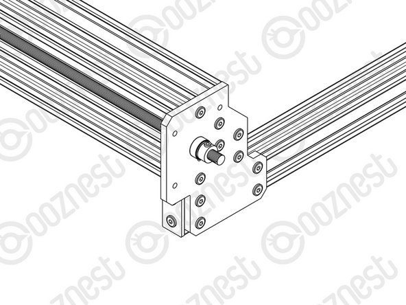
While pushing the 8mm-Clamping-Collar against the 8mm-Shim and F688zz-Bearing into the recess on the Y-End-Plate, tighten the clamping bolt on the 8mm-Clamping-Collar.
-
Push the Flexible-Coupler up against the 8mm-Clamping-Collar. Tighten the clamping bolt first around the Y-ACME-Screw, then the grub screw onto the Y-ACME-Screw.
-
Rotate the Flexible-Coupler a couple of times to insure it is in a un-stressed state. Then rotate it so the grub screw on the stepper motor side is aligned with the flat portion of the motor shaft. Tighten the clamping bolt first around the motor shaft, then the grub screw onto the flat portion of the motor shaft.
-
Repeat for the final NEMA23-Stepper-Motor attaching it to the Y-End Plate-Left on the back right of the machine.
-
-
-
At the front of the machine, onto the two Y-ACME-Screws protruding from the Y-End-Plates slide on a F688zz-Bearing, 8mm-shim, and a 8mm-Clamping-Collar.
-
While pushing the 8mm-Clamping-Collar against the 8mm-Shim and F688zz-Bearing into the hole on the Y-Plate-End-Plates, tighten the clamping bolt on the 8mm-Clamping-Collar.
Note that adding the end caps for the Y ACME screws is not referenced here - these are only added after the screws have been tensioned - but you can add them here to protected the ends . The caps are mounted using the four remaining threaded holes in the Y end plate. The cap has one side with two ‘U’ cut outs that go around the heads of the bolts that were use to join the plate to the C beam.
-
Thanks for following the guide. Any issues, please contact us!
Thanks for following the guide. Any issues, please contact us!
Cancel: I did not complete this guide.
46 other people completed this guide.
4 Comments
Step 3 - The suggested 10mm protrusion of the Acme screw is not enough! By the time you’ve got the thickness of the bearing flange + spacer + the collar there is not enough left to get a proper fixing into the flexible coupler - it needs about 10mm after the collar to go into the flexible coupler. Allowing for this additional protrusion then means that when attempting to fit the motor, the shaft goes all the way though the flexible part of the coupler instead of slightly less than half way and collides with the Acme screw before the motor fixing screws are all the way in (negating the “flexible” concept completely)!
The only answer I could find was to increase the motor fixing distance using additional spacers (5mm washers).
Should the aluminium spacers be a bit longer or the motor shaft a bit shorter I wonder?
Alan Foster - Resolved on Release Reply
Hi Alan - This is not a known issue and should not impede the build of your WorkBee CNC Machine kit I would recommend mounting the Flexible Coupler on the motor loose enough that it cannot spin but is engaged with the flat portion of the Motor Shaft then rotate the ACME Screw through until contact is made with the Shaft then back it out by 1mm as the guide suggests - ~1.0mm (The thickness of a Precision-Shim) between it and the shaft of the NEMA23-Stepper-Motor shaft.
After finishing step 3 for the left Y stepper motor I wasn’t able to repeat the procedure for the right Y stepper motor since trying to move the acme screw by hand to achieve the ~1.0mm proved impossible because the left Y flexible coupler was already tightened to its motor and the whole X-gantry tried to move. I was only able to complete the instructions by assembling both Y motors in tandem. Unless I did something wrong and didn’t realize it.


