
Introduction
This guide goes over connecting to your WorkBee CNC Machine, updating the WorkBee firmware to the latest release.
-
-
Download the latest firmware from: WorkBee Firmware Releases
-
Unzip the folder to somewhere on your computer.
-
Do not unzip any folders inside this one.
-
-
-
The WiFi & Ethernet Duets require a different setup format depending on how you are connecting to it, please follow the appropriate Step for your Workbee.
-
For Wifi Connected to an External Network.
-
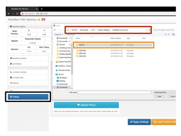
Click Upload under the Settings - General Tab in the Duet Web Control.
-
Open the latest version of the Firmware, navigate to System Settings.
-
Choose the Machine Drive and Size folder.
-
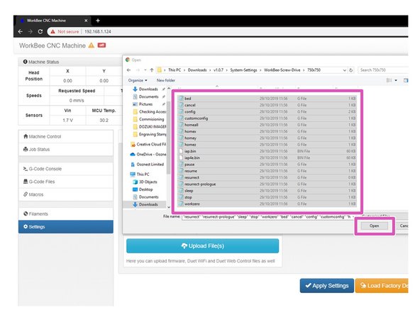
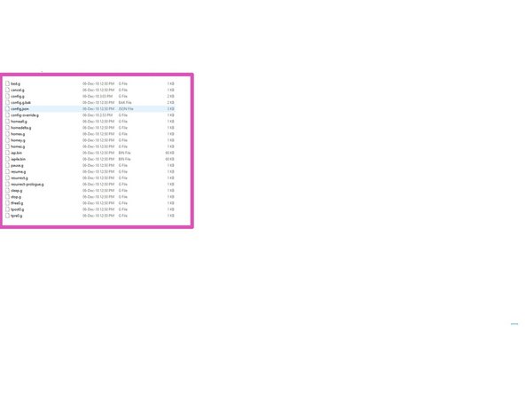
Select all files inside that folder and click open to upload them to the Duet.
-
The controller should automatically reboot after the upload is complete. If not please press the emergency stop button to force restart the controller.
-
-
-
The WiFi & Ethernet Duets require a different setup format depending on how you are connecting to it, please follow the appropriate Step for your Workbee.
-
For Wifi Connected as an Access Point.
-
Click Upload under the Settings - General Tab in the Duet Web Control.
-
Open the latest version of the Firmware, navigate to System Settings.
-
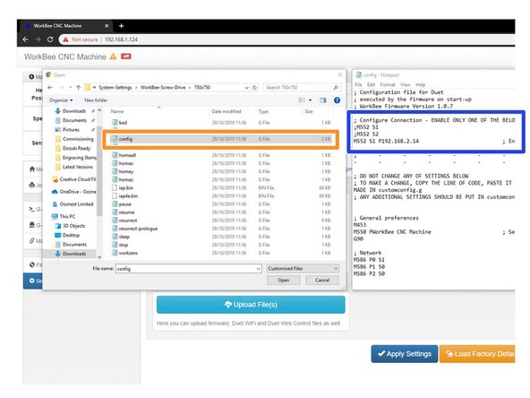
Choose the Machine Drive and Size folder. Once the folder is open right click on config.g and click edit.
-
In Notepad add a semicolon in front of M552 S1 and remove the semicolon from the front of M552 S2, save and close this file.
-
Select all files inside that folder and click open to upload them to the Duet.
-
The controller should automatically reboot after the upload is complete. If not please press the emergency stop button to force restart the controller.
-
-
-
The WiFi & Ethernet Duets require a different setup format depending on how you are connecting to it, please follow the appropriate Step for your Workbee.
-
For Ethernet Connected directly to a computer.
-
Click Upload under the Settings - General Tab in the Duet Web Control.
-
Open the latest version of the Firmware, navigate to System Settings.
-
Choose the Machine Drive and Size folder. Once the folder is open right click on config.g and click edit.
-
In Notepad add a semicolon in front of M552 S1 and remove the semicolon from the front of M552 S1 P192.168.2.14, change IP Address to suit based on the previous completed guide 2. Connecting your Duet to a Network - Ethernet Save and close this file.
-
Select all files inside that folder and click open to upload them to the Duet.
-
The controller should automatically reboot after the upload is complete. If not please press the emergency stop button to force restart the controller.
-
-
-
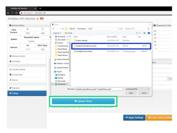
In WorkBee Web Control go to Settings > General
-
Press Upload File
-
Navigate to the unzipped firmware folder and select "Duet2CombinedFirmware.bin"
-
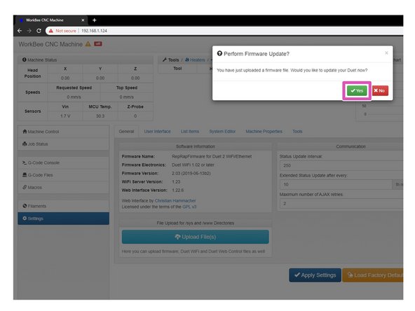
Wait for the file to upload, and press "Yes" on the update prompt.
-
Wait for the update to complete.
-
The controller should automatically reboot after the update is complete. If not please press the emergency stop button to force restart the controller.
-
-
-
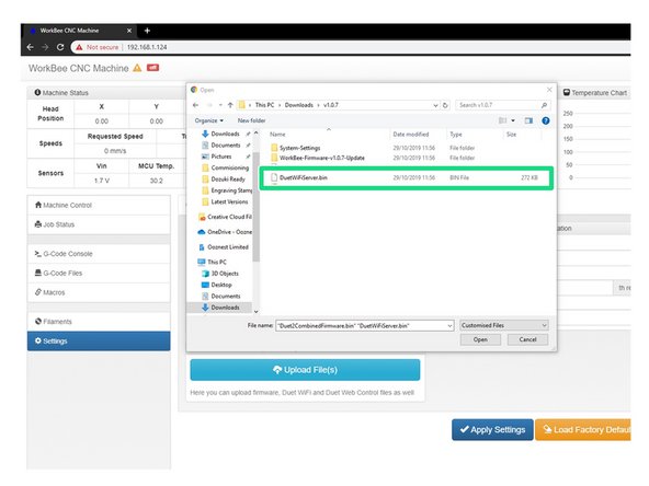
Repeat Step 5 but this time for DuetWifiServer.bin (If applicable)
-
Do not do this step if you have the ethernet version.
-
The controller should reboot automatically after the update is complete. If not please press the emergency stop button to force restart the controller.
-
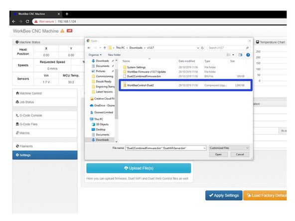
Repeat again for WorkBeeControl.zip this will now update your WorkBee CNC Machine to have the latest WorkBee Control Interface.
Hi Colin,
Thanks for the feedback on the guide. We do have a separate video on connecting with Ethernet cable here: https://www.youtube.com/watch?v=IqPEGNAD...
But your right maybe we should have multiple written guides for all the different options. I will look into doing this.
Ryan
With the Duet2 Ethernet I lost coms with the web control after uploading the SystemSettings files because the config file has no fixed IP address defined and, at least with my PC, refused to play ball as DHCP. In the end I used YAT to send a M552 P192.168.2.14 S1 command and with my network adaptor set with an IP of 192.168.2.11 and gateway of 192.168.2.254 I got coms with the web controller back and was able to edit the config file via Settings/System Editor.
It would be good if the downloads had separate options for WiFi and Ethernet duets with the config files in each set as needed. It might also be easier (at least for the end user) to simply have separate instruction pages for Mac and PC users and split those into pages for WiFi and Ethernet users.
Colin Mill - Resolved on Release Reply
-
-
-
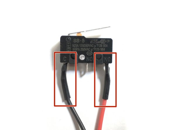
Please check if your limit switches are wired the same as in the image. One wire going to the 'C' terminal and one wire going to the 'NC' terminal. If they are continue with this step. If they are not the same, then this step can be skipped.
-
If your limit switches do not match the image do not be concerned as everything will still operate correctly.
-
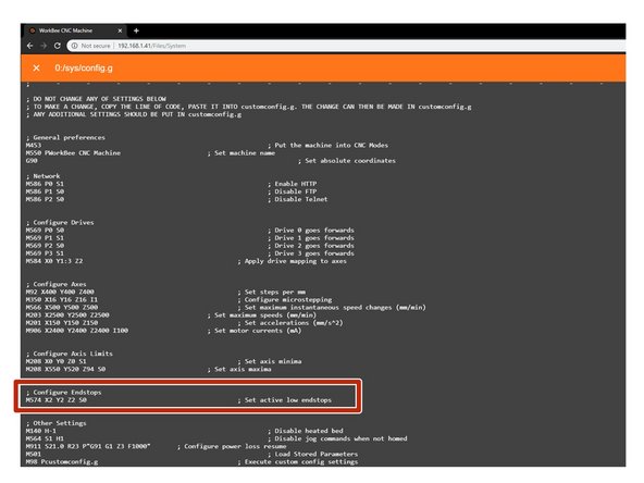
Under File Management open System - Config.g and Copy the Configure Endstops information.
-
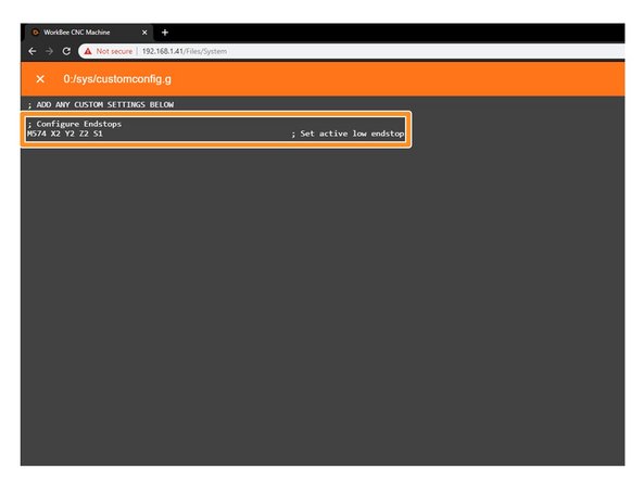
Return back to System and open Customconfig.g and paste in the Configure Endstop Lines changing the S0 to S1 to reflect the NC Terminals.
-
If you have different configurations for each switch please email sales@ooznest.co.uk for further advice.
-
Once complete, Press 'Save' and reboot by pressing the Emergency Stop Button.
-


Thanks for following the guide. Please move onto the next guide to learn how to use your WorkBee CNC Machine. Any issues, please contact us!
Thanks for following the guide. Please move onto the next guide to learn how to use your WorkBee CNC Machine. Any issues, please contact us!
Cancel: I did not complete this guide.
27 other people completed this guide.

13 Comments
Afternoon Ryan
I am trying to configure my Limit Switches as described above. I have pulled across the settings to the CustomConfig file and changes the setting to S1 and reboot, sadly the Sensors do not indicate Triggered when pressed, however the red light at the relevant drive connector goes off. I tried the settings with S0 and all 3 indicate triggered.
Regards
Steve
Steve Moss - Resolved on Release Reply
Hi, @stirlingmw did you manage to get this issue sorted? Please email sales@ooznest.co.uk and we can help you get on your way!
Hi Ryan, I am having trouble that the WorkBee thinks that it is some sort of 3D printer, I have installed the Workbee Screw-Drive-Settings pack and it doesn’t show any of the limit switches in the sensors list and it has all kind of wrong 3d printer stuff all over it.
What would be the best approach of fixing it?
It should be a milling tool
Ville Bask - Resolved on Release Reply
Hi, I think you have missed off the blue section in Step 6. This will make the interface match the above. Best Regards Ooznest.
Hi Ryan, I’m having trouble with homing. You mention a step 10? I can only see up to steps 7. Where can I find the other steps? Thanks
dan cartlich - Resolved on Release Reply
Hi, with our new WorkBee Control, this has allowed us to remove 3 steps. So Step 10 is now Step 7.
Hi Ryan, I keep getting an M120 error code when trying to home x,y and z. Something like “outside working limits” . It just homes in the middle as though there is only a 20mm working area. I’ve set the x and y at 800 and 770, ( I have the 1000mm x 1000mm).
Jonathan Oxborrow - Resolved on Release Reply
Hi,
Thanks for your comment, have you set the X and Y in the homing files in Step 10?
Best Regards
Ryan Lock
Hi Ryan, I have a screw 750x1000. I cannot figure what the Z parameter needs to be set to for homex, homey, homez.
Thanks
Colin Kent
Colin Kent - Resolved on Release Reply