
-
-
Attach the V-Slot-2040-750mm to the back two holes on the Y-Plate-Right-Assembly using 2 x M5-Low-Profile-15mm bolts.
-
Attach the C-Beam-750mm to the four non-threaded holes on the Y-Plate-Right Assembly shown above using 4 x M5-Low-Profile-15mm bolts.
-
-
-
Before the Y-Plate-Left-Assembly can be attached, Tee-Nuts need to be inserted.
-
The Tee-Nuts should be inserted so that the flat face is facing outwards.
-
Insert 2 x Tee-Nuts in to the front facing top slot, 2 x Tee-Nuts in to the front facing bottom slot.
-
Slide the X-Carriage-Assembly onto the C-Beam-750mm in the orientation seen above.
-
Repeat Step 1 for the Y-Plate-Left-Assembly.
-
Recheck the bottom Eccentric-Spacer-6mms on the X-Carriage-Assembly to make sure they are touching the rail, there is no wobble, and that the X-Carriage-Assembly runs smoothly along the whole length of the C-Beam-750mm.
-
Place the X-Gantry Assembly onto a flat table. Check both Y-Plates are sitting flush with the table. Loosen the extrusions and adjust if needed.
Before screwing on the Y-Plate assembly with the stepper motor attached to the to the two extrusions, it is worth looking at The Electronics Assembly, Section 1, Step 4. Fix the Y-Axis-Moving-End to the Y-Plate-Left assembly now. It will save a lot of frustration later when you realise access to a blot is very limited…………
Jonathan Pearce - Resolved on Release Reply
If you are unsure where to put the T-nuts, look at step 4 as the are used to fix the corner brackets to the plates and beams.
Also for this step, I found it easier to take off the stepper motor to give better access to the bolts used to join endplates to beams.
Jonathan Pearce - Resolved on Release Reply
-
-
-
Looking at the Y-Plate-Left, adjust the X-ACME-Screw so the end is on the extrusion side of the Y-Plate-Left.
-
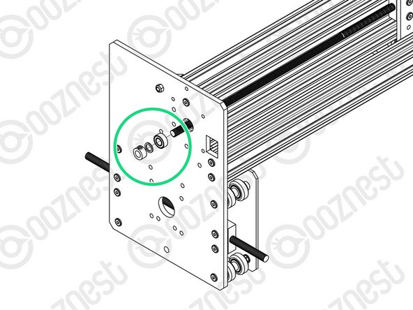
In the gap between the Y-Plate-Left and Flexible-Coupler, insert a F688zz-Bearing, 8mm-Shim, and 8mm-Clamping-Collar. With the F688zz-Bearing closest to the Y-Plate-Left, seated inside the hole.
-
Adjust the X-ACME-Screw back through the F688zz-Bearing, 8mm-Shim, and 8mm-Clamping-Collar, until it touches the NEMA 23-Stepper-Motor shaft.
-
While pushing the 8mm-Clamping-Collar against the 8mm-Shim and F688zz-Bearing into the recess on the Y-Plate-Left, tighten the clamping bolt on the 8mm-Clamping-Collar.
-
Tighten the grub screws on the Flexible-Coupler. Make sure one is on the flat portion of the motor shaft.
-
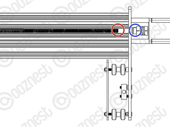
On the outside of the Y-Plate-Right slide on a F688zz-Bearing, 8mm-Shim, and 8mm-Clamping-Collar. Inset the F688zz-Bearing into the hole.
-
While pushing the 8mm-Clamping-Collar against the 8mm-Shim and F688zz-Bearing into the recess on the Y-Plate-Right, tighten the clamping bolt on the 8mm-Clamping-Collar.
-
-
-
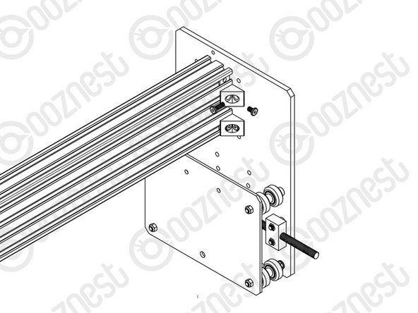
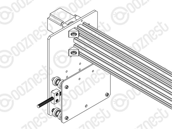
Attach an Angle-Corner to the Y-Plate-Right-Assembly & the front facing top slot of the C-Beam-750mm. A M5-Low-Profile-8mm screws into the Tee-Nut previously inserted, and a M5-Low-Profile-15mm goes though the Angle-Corner and attaches to a M5-Nyloc-Nut on the outside of the Y-Plate-Right-Assembly.
-
Repeat this for the other 3 Angle-Corners in the positions shown above.
-


Thanks for following the guide. Any issues, please contact us!
Thanks for following the guide. Any issues, please contact us!
Cancel: I did not complete this guide.
49 other people completed this guide.

If you bought a larger machine than 750mm, the instructions here could confuse because you won’t own a 750mm c beam or a 750mm v-slot 2040. Ive been looking through the rest of the guide and it looks like for this step you will need to use the v-slot 2040 that is the same length as the c beams you have been sent e.g. I have been sent 3x1000mm c beams 1x1000mm v-slot-2040 2x995mm v-slot-2040 and 2x915mm v-slot-2040 so I will be using the 1000mm v-slot-2040.
Im not100% on this but im just about to crack on with it so ill post a comment if I find out later this is wrong.
Daniel Cox - Resolved on Release Reply